
ON THIS PAGE:
What Is Roof Ventilation?
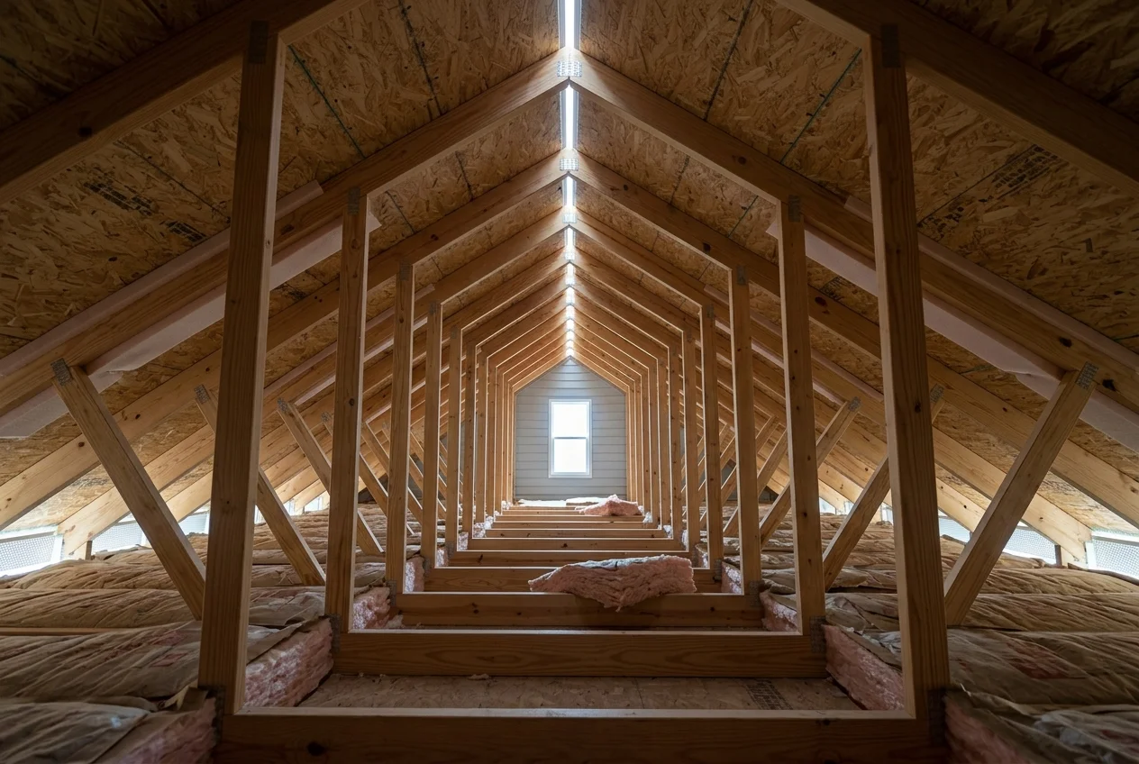
Roof ventilation is the controlled exchange of air between the outdoors and the space directly under the roof deck — the attic, or the enclosed rafter space on a cathedral ceiling. It works by admitting outside air through openings at the lowest edge of the roof and releasing air through openings at the highest point, using natural pressure differences rather than motors. A house without working roof ventilation still has air in the attic; it just has the wrong air, sitting too long, at the wrong temperature, carrying the wrong amount of moisture.
The complete assembly — every intake opening, every exhaust opening, the clear path between them, and the rules that keep them sized correctly — is the roof ventilation system. Two halves define it. Roof intake vents at the eaves let cool, dry outside air in. Roof exhaust vents at or near the ridge let warm, moist air out. Between them sits the attic floor, which separates the system from the living space below and is where nearly all of the moisture that loads the attic originates. Because the system is sized against that floor area, understanding roof ventilation always begins with one measurement: the square footage of the attic floor being vented.
What Roof Ventilation Is Not
Roof ventilation is not the home's HVAC system, not a substitute for air sealing, and not the same thing as a power vent — although powered and solar exhaust products exist and appear in the tables below. The default roof ventilation system in residential construction is entirely passive: no electricity, no moving parts, no controls. It depends on geometry and physics — low openings, high openings, an unobstructed channel between them, and enough net open area to satisfy the code ratio for that attic floor. A power fan is an optional supplement for stubborn conditions, never the foundation of the design.
It is also not insulation's job. Insulation slows heat flow through the attic floor; it does nothing to move air through the attic volume. The two are designed as a pair — insulation and air sealing on the floor, ventilation above it — and confusing them leads to the most common field failure in the whole subject: insulation stuffed into the eave that blocks the intake vents while the vent count on the roof looks perfect.
The Vocabulary Used in This Guide
Terminology varies by region: across the United States and Canada the subject is called roof ventilation or attic ventilation; in the United Kingdom, Australia, and New Zealand the same content is usually roof ventilation or loft ventilation, and the eave openings are called soffit vents in all of them. The physics, the code ratios, and the arithmetic in this guide are identical in every region — only the local code document changes. Throughout this guide, roof ventilation system means the whole assembly of intake and exhaust; roof ventilation airflow means the actual air path and volume moving through it; balanced roof ventilation means a system whose intake capacity equals or exceeds its exhaust capacity; net free area (NFA) means the open area left after a vent's screen, louvers, and frame are subtracted; and 1/150 and 1/300 are the two code ratios that set how much net free area the attic floor requires. Learning these names once is enough — they appear the same way in the code, in manufacturer instructions, and at the supply counter.
Why Roof Ventilation Matters
Every attic experiences two opposing seasonal loads, and a roof ventilation system exists to carry both away before they damage anything. The heat load is a summer problem; the moisture load is a year-round problem that peaks in winter. Both are measured against the same space, and both get worse as net free area shrinks or the airflow path gets blocked.
Summer: Heat That Bakes the Roof Deck
On a sunny day the roof deck absorbs solar radiation and re-radiates it into the attic, where the air has nowhere to go if ventilation is poor. Attic temperatures can climb far above outdoor ambient values, and that trapped heat works against the house from two directions: it radiates through the attic floor into the living space, increasing cooling load, and it keeps the underside of the shingles hot for hours after sunset. Asphalt shingles age thermally — sustained high temperatures accelerate the loss of volatiles that keep them flexible, which is why shingle manufacturers tie warranty validity to adequate ventilation and why inspectors treat a hot, stagnant attic as a defect rather than a nuisance. Proper roof ventilation airflow flushes that heat out continuously: air enters at the soffit, warms as it travels up the underside of the deck, and leaves through the exhaust at the peak.
Winter: Moisture That Condenses on Cold Sheathing
Moisture loads the attic from below every day — water vapor diffuses and leaks through the ceiling plane from bathrooms, kitchens, laundry, combustion appliances, and simply from occupants breathing. In an unventilated or under-ventilated attic that vapor reaches the cold roof sheathing and condenses into liquid water, because the sheathing is the coldest surface in the assembly. The damage compounds: wet sheathing rots, wet insulation loses R-value, nail tips rust and "shingle pops" appear, and mold colonies establish on the framing. Attic ventilation defeats this by continuously replacing the loaded indoor air with dry outdoor air and by keeping the sheathing temperature closer to outdoor temperature, so vapor is swept out before it saturates anything. This is the load that makes winter ventilation more important than summer ventilation in cold climates — and it is the reason the 1/300 code exception is conditional on a vapor retarder in Climate Zones 6, 7, and 8.
Ice Dams
Ice dams form when heat escaping from the living space melts snow on the upper roof, and the meltwater refreezes on the colder overhang at the eave. Ventilation attacks the cause rather than the symptom: a ventilated attic stays close to outdoor temperature, the sheathing under the snow does not warm above freezing, and snow melts from above (sunlight) rather than from below (house heat). No ventilation guide fixes a badly air-sealed ceiling on its own — air sealing the attic floor is the first line of defense — but ventilation is what keeps the roof deck cold once the heat is stopped.
What the Codes Say
The requirement is not optional advice. The International Residential Code requires enclosed attics and enclosed rafter spaces to have cross ventilation for each separate space, through openings protected against rain and snow, sized by net free area against the vented floor area. The same principle appears in regional codes worldwide. When a roof ventilation system is missing, blocked, or unbalanced, the failure shows up later as shingle callbacks, sheathing rot, mold remediation, or energy complaints — all of which cost far more than the soffit panels and ridge vent that would have prevented them.
Roof Ventilation Airflow: The Stack Effect
Roof ventilation airflow runs on two natural drivers working together: the stack effect (buoyancy) and wind pressure. Understanding both explains why vent placement matters more than vent count, and why balanced roof ventilation is not a stylistic preference but a mechanical requirement.
The Stack Effect
Air warmed by the attic floor and roof deck becomes less dense and rises. When the only escape is at the top of the roof, that rising air exits through the exhaust vents, and the resulting pressure difference draws replacement air in through the lowest openings — the soffit and undereave vents. This is the stack effect: warm air out at the ridge, cool air in at the eave, driven entirely by temperature difference. It works year-round, works without wind, and gets stronger as the vertical distance between intake and exhaust grows and as the temperature difference increases. Two consequences follow immediately. First, intake and exhaust must be at different heights — that vertical separation is the engine. Second, the path between them must be open along the entire attic floor: any ridge vent starved of eave intake simply pulls its replacement air from whatever opening is nearest, which is usually a ceiling gap in the living space below.
The Wind Effect
Wind moving across a roof creates pressure differences: positive pressure on windward slopes pushes air in, negative pressure on leeward slopes and over the ridge pulls air out. A well-designed system harvests this for free — windward soffit vents admit air, leeward and ridge vents exhaust it. Wind-driven flow also explains two design decisions. Gable-end louvers work only when wind blows, switching between intake and exhaust roles with wind direction, which is why they are unreliable as a sole exhaust strategy. And ridge vents with external baffles exploit the low-pressure zone air creates as it passes over the ridge, actively pulling attic air out in still conditions — the reason a shingle-over ridge vent outperforms a plain slot in the same location.
The Continuous Channel
The two drivers only pay off if air can travel the full distance. The airflow path runs from the soffit opening, up between the rafters above the insulation, along the underside of the sheathing, and out the ridge. That path is destroyed by insulation blown into the eave, by storage boxes stacked against the deck, by missing or crushed rafter baffles, and by framing details that wall off one rafter bay from the next. The codes address this directly: insulation must be held back at least 1 inch from vent openings, and a 1 inch clear space must be maintained between insulation and roof sheathing, with baffles used to hold the channel open. A roof ventilation system with the right net free area and a blocked channel has the same effective airflow as one with no vents at all.
From Airflow to CFM
Airflow through passive vents is often expressed in cubic feet per minute even though nothing is being measured in real time. The standard conversion uses the design velocity for natural ventilation — 750 feet per minute: required airflow (CFM) ≈ required net free area in square feet × 750. A 1,500 sq ft attic at the 1/150 ratio needs 10 sq ft of net free area, which corresponds to roughly 7,500 CFM of designed airflow capacity; at the 1/300 ratio the same attic needs 5 sq ft, about 3,750 CFM. CFM becomes the sizing unit for powered exhaust products, where a fan is rated in CFM rather than square inches — but for passive soffit and ridge vents, net free area remains the number every calculation uses.
Roof Intake Vents and Roof Exhaust Vents
Every roof ventilation system is built from the same two families of components, and the families are not interchangeable. Roof intake vents exist only at the bottom of the assembly; roof exhaust vents exist only at the top. Placing them wrong — an intake on the upper slope, an exhaust in the eave — inverts or shortens the airflow path and can pull the whole system into reverse on a windy day.
Roof Intake Vents: Where the Air Enters
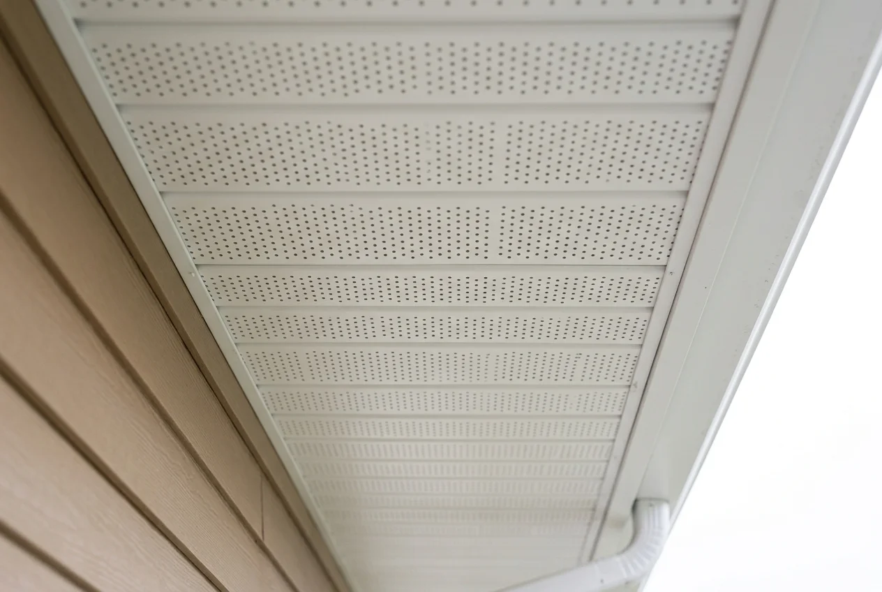
Intake vents live at the eave because that is the lowest, coolest, driest air available and because the eave is where the rafter bays begin. The family includes:
- Continuous soffit vents. Perforated or gridded sections running the full length of the soffit — either vented panels replacing solid ones or strip vent fitted into a slot. They deliver the most uniform airflow because every rafter bay gets its own share, and they are the default intake for new construction.
- Individual soffit vents. Round or rectangular vents punched into an existing solid soffit at intervals. They work for retrofits where replacing the whole soffit panel is impractical, but capacity comes in lumps: airflow exists at each vent and nowhere between them.
- Undereave and eyebrow vents. Discrete vents mounted on the underside of the overhang itself, used where the soffit material cannot be perforated.
- Fascia vents. Vented strips at the fascia board, drawing air in over the top of the fascia. They suit boxed-eave details where there is no open soffit plane.
- Drip-edge intake vents. A modified eave metal profile with a vented slot. They are the last-resort intake for houses built with no overhang at all — effective, but limited in net free area per foot, which frequently pushes such designs back to the stricter 1/150 ratio.
- Mid-roof intake. Vents installed higher on the slope when no low intake exists. They are a remedial measure: intake should always be as low as possible so the replacement air sweeps the entire attic floor instead of entering halfway up.
Roof Exhaust Vents: Where the Air Leaves
Exhaust vents must sit in the upper portion of the roof — at the ridge, within the top third of the slope, or at the gable end — because that is where the warmest, most buoyant air collects. The family includes continuous ridge vents (installed under the cap shingles along the peak), static box vents (individual low-profile vents distributed across the upper roof field), wind turbines (roof-mounted cowls that spin to draw air), gable-end louvers (mounted in the vertical wall of a gable), power attic ventilators (electric fans with thermostats or humidistats), solar-powered attic fans, and off-ridge or hip vents for roofs with too little ridge for a continuous run. Each is described with its capacity in the next section; the one rule that binds all of them is that only one exhaust type serves a given attic.
Why Intake and Exhaust Vents Must Work as a Pair
The words intake and exhaust vents describe one machine with two ports. Exhaust creates the pressure differential that intake satisfies, and intake provides the replacement air that exhaust removes. Shortage at either end degrades the same way: with too little exhaust, warm air pools at the ridge no matter how much soffit area exists; with too little intake, the exhaust pulls from the house through every ceiling crack it can find — recessed lights, hatch gaskets, plumbing chases — dragging conditioned air out of the living space and, in houses with atmospherically vented appliances, potentially backdrafting combustion equipment. The sizing arithmetic in this guide therefore never stops at a single total: it always divides the required net free area into an intake share and an exhaust share, sizes both, and checks that intake capacity is at least equal to exhaust capacity at every point.
Vent Types Compared
The tables below compare every exhaust and intake option with its typical rated net free area, the roof conditions it suits, and the constraints that decide it. NFA figures are planning ranges — the stamped rating on the actual product is the authority, and a single product line can vary by 20% from the values here.

Exhaust Vent Comparison
| Exhaust Type | Typical Rated NFA | Best Suited To | Constraints |
|---|---|---|---|
| Continuous ridge vent | 18–20 sq in per linear foot | Most roofs with a full-length ridge; the default exhaust for gable roofs | Needs continuous ridge plus matched soffit intake; never combined with other exhaust types; runs usually stop short of hips and obstructions |
| Static box vent (turtle vent) | 50–65 sq in per vent | Roofs with short or broken ridges; distributed exhaust across the upper field | Penetrates the deck at every unit; spread evenly and never mixed with a ridge vent on the same attic |
| Wind turbine (whirlybird) | 100–150 sq in equivalent per vent | Breezy regions; budget exhaust where ridge length is limited | Moving parts wear, freeze, and leak at the bearing; effective output depends on wind |
| Gable-end louver | As low as ~37% of gross opening | Cross-ventilation at the gable wall; intake or exhaust depending on wind direction | Wind-dependent; must be sealed when a ridge vent serves the same attic; useless on hipped ends |
| Power attic ventilator | Sized in CFM (about 0.7 CFM per sq ft of attic floor) | Hot climates with chronic heat buildup after passive measures are optimized | Requires make-up intake sized to its CFM; never combined with ridge vents; can depressurize the living space if intake is short |
| Solar attic fan | CFM-rated, typically 10–20% below wired equivalents | Locations without available circuit wiring; supplemental exhaust | Same balance rules as powered fans; output falls with sun angle and panel soiling |
| Off-ridge / hip vent | Varies by product; installed in linear feet | Hip roofs and complex cut-up roofs with little usable ridge | Serves as the sole exhaust for that attic; still requires full soffit intake |
Intake Vent Comparison
| Intake Type | Typical Rated NFA | Best Suited To | Constraints |
|---|---|---|---|
| Continuous soffit strip or vented panel | 5–9 sq in per linear foot (9 typical) | New construction and full-soffit retrofits; the most uniform intake available | Requires baffles at each rafter bay so insulation cannot block the channel |
| Individual soffit vents | 4×16 in ≈ 28 sq in; 16×8 in ≈ 50–65 sq in each | Retrofitting a solid soffit without replacing panels | Airflow concentrated at each unit; space evenly on both eaves (typically every 4–6 ft) to avoid dead zones |
| Undereave / eyebrow vent | Product-rated, commonly 25–50 sq in each | Soffits that cannot be perforated | Lower capacity per opening than continuous systems; count them individually against the intake share |
| Fascia vent | ≈ 8–9 sq in per linear foot | Boxed-eave details with no open soffit plane | Keep clear of gutter debris; verify the detail does not trap the slot behind the gutter |
| Drip-edge intake vent | ≈ 6–10 sq in per linear foot | Houses built with no eave overhang | Modest capacity; designs relying on it commonly fall under the stricter 1/150 ratio |
| Mid-roof intake vent | Product-rated (often 50–100 sq in each) | Remedial work where no low intake can be created | Enters air partway up the slope, so part of the attic floor never sees the incoming air |
The Recommended Pairing
Continuous ridge vent plus continuous soffit intake — the soffit and ridge vents pairing — is the standard recommendation from every major shingle manufacturer and the default answer wherever the geometry allows it. It delivers uniform airflow at every rafter bay along the entire roof plane, it has no moving parts, the ridge vent is hidden under cap shingles, and it avoids the multiple deck penetrations that individual exhaust vents require. Every alternative in the tables above exists because a specific roof condition denied the design one of its two ends: no ridge (hip roofs take off-ridge or turbine exhaust), no overhang (no-overhang houses take fascia or drip-edge intake), or no common attic (vaulted ceilings take per-bay channels). Choose the pairing first, then reach for alternatives only where the geometry forbids it.
Net Free Area: The Number That Counts
Every building code, every manufacturer instruction, and every sizing calculation in this guide uses net free area — not the vent's face size, not the hole cut for it, and not the vent count. NFA is the open area that actually passes air after the insect screen, the louvers, the frame, and any filter baffle are subtracted. It is almost always dramatically smaller than the nominal dimension suggests, and the gap between gross and net is the single largest source of error in roof ventilation sizing.
Gross Area vs. Net Free Area
A 16 inch by 8 inch soffit vent measures 128 sq in of gross opening. Behind its screen and louvers it typically flows about 50 to 65 sq in — roughly half. A 24 inch square gable louver has a 576 sq in face and may be rated at 300 sq in or as low as 213 sq in depending on the screen. Screened eave openings themselves are often only about 60% free area, so a raw hole cut for a screened vent needs its gross size divided by roughly 0.6 to find what the screen will actually deliver. The pattern holds across the entire product family: NFA runs from about 37% of gross on heavily louvered gable vents to perhaps 70% on a clean continuous strip. Sizing from the dimension printed on the package routinely leaves an attic with half the airflow it needs while every vent-count check on paper passes.
NFA Reference Table
| Product | Typical Rated NFA | Basis of Rating |
|---|---|---|
| Continuous ridge vent | 18–20 sq in per linear foot | Per foot of installed ridge, under cap shingles |
| Continuous perforated soffit | 5–9 sq in per linear foot (9 typical) | Per foot of soffit run |
| Round soffit vent, 4–6 in diameter | 10–18 sq in per vent | Per unit |
| Rectangular soffit vent, 8×16 in | 50–75 sq in per vent | Per unit |
| Undereave louver, 4×16 in | ≈ 28 sq in per vent | Per unit |
| Static box vent | 50–65 sq in per vent | Per unit |
| Wind turbine, 12 in | 100–150 sq in equivalent | Per unit at operating wind speed |
| Gable louver, 24×24 in | ≈ 37–50% of gross opening | Screen and louver dependent |
| Drip-edge intake vent | 6–10 sq in per linear foot | Per foot of eave |
The stamped rating is the authority. Manufacturers publish NFA on the package and in their evaluation reports, and cheap vents frequently deliver less than their nominal size while premium baffled ridge products exceed it. When a product line has been selected, enter its printed NFA into the sizing arithmetic; the ranges above are for planning before a product is chosen.
Why NFA Drives Everything
Because the code is written in net free area, NFA converts a measurement of the attic floor directly into a measurement of products. Required NFA (sq in) = attic floor area × 144 ÷ ratio. From there, product quantities fall out of division: ridge length = exhaust NFA ÷ NFA per foot; soffit length = intake NFA ÷ NFA per foot; unit count = vent-share NFA ÷ NFA per unit, rounded up to the next whole vent because a fraction of a vent cannot be installed. Every step preserves the same discipline — round lengths and counts up so the installed capacity meets or exceeds the requirement, never down.
Code Ratios: 1/150 and the 1/300 Exception
The amount of roof ventilation an attic requires is set by two ratios in the residential code, expressed in IRC Section R806. The baseline is 1/150; the reduced 1/300 is an exception with conditions attached to both its halves. Knowing which one applies determines the entire material count, so it is settled before any product is selected.
| Requirement | Formula | Conditions | Typical Application |
|---|---|---|---|
| Baseline: 1/150 | Required NFA (sq ft) = attic floor area ÷ 150 | None — applies whenever the exception is not fully met | The default in many local codes; required when there is no low intake, no vapor retarder in cold climates, or an unbalanced layout |
| Exception: 1/300 | Required NFA (sq ft) = attic floor area ÷ 300 | Both: (1) in Climate Zones 6, 7, 8 a Class I or II vapor retarder on the warm-in-winter side of the ceiling; (2) 40–50% of the required area from upper vents not more than 3 ft below the ridge, balance in the bottom third of the attic | Balanced soffit-and-ridge systems on homes meeting the placement and (in cold zones) vapor-retarder conditions |
How the Exception Is Actually Evaluated
Two conditions, not one — the wording changed from "one or more" to "both" in the 2018 edition, and designs grandfathered on the older text are a common source of non-compliance on renovations. The vapor-retarder condition applies only in Climate Zones 6 through 8: in Zones 1 through 5 a balanced high-and-low layout alone qualifies for 1/300. The placement condition is geometric and verifiable on site: upper ventilating area between 40 and 50 percent of the total, located no more than 3 feet below the ridge or highest point measured vertically (framing conflicts permitting a bit more), with the balance in the bottom one-third of the space. Intake at 50 to 60 percent of the total satisfies the placement test with margin and is the configuration most soffit-and-ridge systems naturally achieve.
The Other Half of R806: Openings and Clearance
Section R806.1 governs not just quantity but construction. Ventilation openings must have a least dimension between 1/16 inch and 1/4 inch; larger openings must be covered with corrosion-resistant wire cloth, hardware cloth, or perforated vinyl carrying the same 1/16 to 1/4 inch opening size — this is the pest-and-rain screen that reduces gross area to net free area in the first place. Openings must lead directly to outside air and must be protected against birds, rodents, and snakes. Each separate enclosed space — an attic over the main house, a garage ceiling under its own roof, an enclosed porch — must be cross-ventilated on its own; one shared calculation does not cover several disconnected spaces. Insulation must be held back at least 1 inch from every vent opening, with a 1 inch clear channel between insulation and sheathing maintained through the space, which is what rafter baffles provide.
Which Ratio to Use in Practice
Start with the local code, because the authority having jurisdiction decides — some jurisdictions adopt 1/150 across the board regardless of layout, and the FHA guideline commonly used by manufacturers is 1/300 with an even split. Where the choice is open: use 1/300 for new construction with a continuous soffit-and-ridge system and a vapor retarder already in the design; use 1/150 when retrofitting an existing house without adding a vapor retarder, in humid climates where the extra moisture margin matters, or whenever the layout cannot demonstrate the 40–50% upper-vent placement. When in doubt, size to 1/150 — the additional net free area costs little at the soffit and nothing at the ridge, and it keeps the design compliant under either interpretation.
Balanced Roof Ventilation Sizing
Balanced roof ventilation means one thing arithmetically: installed intake net free area is greater than or equal to installed exhaust net free area, with the total meeting the code ratio. The ratio sets how much; the split decides how that total divides between the eave and the ridge. Sizing a system is therefore three steps — total, split, convert — and every reputable method, from a spreadsheet to a manufacturer calculator, follows the same sequence.
Step 1: Total Required Net Free Area
Required NFA (sq in) = attic floor area (sq ft) × 144 ÷ ratio. The division by 150 or 300 produces square feet of open area; multiplying by 144 converts square feet to square inches, which is how vent products are rated. A 1,500 sq ft attic at 1/150 needs 1,440 sq in; the same attic at 1/300 needs 720 sq in. This total is non-negotiable — it is the number the inspector checks against.
Step 2: The Intake and Exhaust Split
| Split | Intake Share | Exhaust Share | Where It Is Used |
|---|---|---|---|
| 50 / 50 | 50% of total NFA | 50% of total NFA | The code minimum — half the area high, half low, which is what the 1/300 placement condition allows at its limit |
| 60 / 40 | 60% of total NFA | 40% of total NFA | The commonly recommended intake-heavy split: positive attic pressure keeps wind-driven rain and snow from being drawn in through the exhaust |
| Intake exceeds exhaust | More than the exhaust share | Whatever the exhaust product provides | Always acceptable — surplus intake recirculates harmlessly; a deficit of intake never does |
Two constraints bind the split. First, intake never falls below 50% of the total — anything less forces replacement air to come from the house. Second, the 1/300 exception's own placement rule (40–50% in the upper vents) means exhaust must stay under half of the required area when that ratio is being claimed, which lines up exactly with the 60/40 recommendation: exhaust at 40% sits comfortably inside the allowed upper range while intake at 60% clears the "at least half" test with margin.
Step 3: Convert Each Share to Products
Exhaust: ridge linear feet = exhaust NFA ÷ the ridge vent's rated NFA per foot. At 18 sq in per foot, a 576 sq in exhaust share needs 32 linear feet. If the house's ridge is longer than that — which it almost always is — running the vent the full ridge length is standard practice and simply provides capacity above the minimum; it also keeps the installation continuous and visually clean. Intake: soffit linear feet = intake NFA ÷ the soffit product's rated NFA per foot. At 9 sq in per foot, an 864 sq in intake share needs 96 linear feet total, typically divided evenly between the two eaves — 48 feet per side on a house with 50-foot eaves. Individual vents convert the same way with unit counts rounded up: vents = share NFA ÷ NFA per vent, then divided across both eaves. Convert lengths up to the next fraction actually installable, never down.
The Balance Check
Finish every design with a check that ignores the requirement and looks only at what will actually be installed: compare provided intake capacity against provided exhaust capacity. On a full-length soffit and ridge installation both sides usually land near each other (900 sq in of soffit against 900 sq in of ridge on a typical ranch house) — balanced with a slight intake margin once the ridge stops short of hips. When the exhaust chosen is a power fan, the check extends to make-up air: passive intake net free area should cover at least 1 square foot per 300 CFM of fan capacity so the fan draws from outside rather than from the ceiling plane below. If provided intake comes in below provided exhaust on the check, fix it by adding intake or trimming exhaust — never by accepting the shortfall.
Roof Ventilation by Roof Shape
The sizing arithmetic never changes, but the geometry that delivers intake and exhaust changes with every roof form. The same attic area and code ratio can require completely different products depending on how much ridge, how much overhang, and how many separate spaces the roof contains.
Gable Roofs
The ideal case. A gable roof offers a continuous ridge for the full length of the building and continuous overhangs on both eaves, which is exactly what the soffit-and-ridge pairing needs: exhaust runs the ridge (stopping about a foot short of each end and clear of hips or obstructions), intake runs both eaves, and every rafter bay sits directly on the airflow path. Nothing in this guide needs adjusting for a straightforward rectangular gable — the worked example at the end of this page is built on one.
Hip Roofs and Cut-Up Roofs
A hip roof's ridge is short — building length minus building width — and on square footprints it disappears entirely, leaving no continuous peak to vent. Exhaust must then come from off-ridge products: static box vents distributed across the upper third of each slope, wind turbines, or a purpose-made hip vent running along one or more hips. Soffit intake still runs the full perimeter eave as normal. The constraint is placement: whatever exhaust is chosen must sit in the upper portion of the roof — within about 3 feet of the ridge or highest point to qualify as an upper vent for the 1/300 exception — and the units must be spread evenly so no quadrant of the attic relies on a single hole. Complex cross-gable and dormered roofs inherit the same logic per section, with the added discipline that each enclosed space must be vented independently.
Vaulted and Cathedral Ceilings
Where the ceiling is applied directly to the underside of the rafters there is no common attic — the ventilated space is the narrow rafter cavity itself, and it is divided bay by bay by the rafters. Each bay becomes its own ventilation run: air enters the soffit, travels through a vent chute or baffle that holds the insulation down, and exits at a slot by the ridge, with a clear 1 inch between insulation and sheathing for the full length. One blocked bay stalls that bay only, which is why vaulted systems fail one rafter bay at a time and why continuous soffit panels feeding every bay matter more here than anywhere else. The area used in the ratio is the sloped area of the vented space, not the floor footprint.
Houses With No Overhang
Wall-to-wall roof edges deny the design its natural intake location. The solutions, best first: fascia vents at the eave detail, a vented drip-edge profile, or — where low intake truly cannot be created — gable or mid-roof intake as a fallback. When intake cannot be provided at the eave, most codes fall back to the 1/150 ratio for that space, because the low-vent half of the balanced-layout exception can no longer be satisfied. This is the one roof shape where the code arithmetic itself changes, and it is worth confirming with the building department before sizing.
Garages, Porches, and Multi-Space Roofs
R806.1 requires cross ventilation for each separate space. A garage ceiling framed tight under its own roof is a separate space from the house attic above it even when they share a ridge line; a porch roof with a closed soffit and its own rafter cavity is another. Each gets its own area calculation, its own intake, and its own exhaust — sized separately, not averaged together. The classic failure is a beautifully ventilated main attic whose garage bay underneath was sealed, insulated to the deck, and left to rot in its own vapor.
Installation Rules That Make It Work
A correct calculation installed carelessly produces the same outcome as no ventilation at all. Six rules decide whether the airflow the arithmetic promised actually appears.
1. Keep the Channel Open
Insulation must be held back a minimum of 1 inch from every vent opening, and a clear 1 inch space must run between the insulation and the roof sheathing for the whole ventilated space. Rafter baffles (vent chases) — rigid or foam channels stapled from the eave to well above the top plate — hold both clearances at once. Without them, blown insulation migrates into the eave during installation and burial of the soffit vent follows months later as the insulation settles. This is the most common failure in existing houses: the vent count on the roof is right, the intake under the eave is packed solid, and the system draws from the ceiling instead.
2. Provide One Exhaust Type Only
Never mix exhaust products above a shared ceiling plane. A ridge vent paired with an existing box vent, turbine, or open gable louver short-circuits: the exhausts exchange air with one another through the path of least resistance — usually over the hottest, uppermost part of the roof — while the soffit air never rises to replace it. The lower deck stays stagnant no matter how much net free area is installed. When converting a house to a ridge vent, remove the old box vents, cap them, or seal the gable louvers as part of the same job, and confirm the shingle manufacturer's instructions accept the mixing state (most do not, and warranty claims have been denied on exactly this point).
3. Distribute Openings Evenly
Continuous products distribute automatically — every inch of continuous soffit or ridge vent flows. Unit products must be spaced deliberately: individual soffit vents at intervals of roughly 4 to 6 feet along both eaves, mirrored side to side; box vents spread across the upper field rather than clustered near one end. Concentrating openings on one side creates a dead zone on the other, where stagnant air sits against the deck regardless of the totals. Asymmetry also skews the intake-to-exhaust balance across the plan: one windward eave carrying all the intake means a crosswind can stall the whole circuit.
4. Locate Exhaust High and Intake Low
Upper vents belong within 3 feet of the ridge — the top third of the roof plane — and lower vents belong at the eave or cornice. The vertical separation is the stack engine; compressing it (exhaust halfway down the slope, intake only at mid-roof) reduces both the driving pressure and the volume of attic the airflow path sweeps. On roofs with hips and valleys, stop ridge vent runs about 12 inches clear of those intersections and of any skylight, chimney, or other obstruction, and keep the ridge slot continuous otherwise — a ridge vent interrupted at every other rafter bay delivers far less than its rating.
5. Size Powered Exhaust Against Its Make-Up Air
Power and solar attic fans are sized in CFM, but their intake is still sized in net free area: provide at least 1 square foot of passive net free area per 300 CFM of fan rating, delivered through soffits at the low end of the system. A fan without make-up air simply pulls living-space air through the ceiling — raising cooling bills, defeating the air sealing below, and, in houses with atmospherically vented water heaters or furnaces, creating a backdraft hazard that turns an efficiency upgrade into a safety defect. Fans should also be the second step, not the first: air seal and balance the passive system, then add powered exhaust only where heat still builds.
6. Verify Against Local Code
The ratio in the adopted code governs — 1/150 or 1/300, and some jurisdictions amend the exception entirely. Manufacturers publish their own guidance (the FHA-based 1/300 with an even split is common), but the authority having jurisdiction can require more. Confirm the ratio, confirm whether a vapor retarder is credited for the 1/300 claim, and record the product NFA ratings used, so the installed capacity can be demonstrated against the requirement at inspection rather than argued from a catalog.
Settle the plan while the roof is open. The layout, the product choices, and the calculation belong to the same conversation as the shingle replacement itself: soffit panels, eave prep, and rafter baffles go in before insulation and before the roof deck is closed, and a shingle-over ridge vent is cut into the ridge and shingled over as part of the same re-roof. Retrofitting later means lifting a finished course of caps to cut the deck blind, and retrofitting intake means pulling gutters and soffit trim off completed work. Specify the vent type and both shares together with the roofing material list, so intake, exhaust, and every baffle arrive on site with the crew instead of after them.
Common Roof Ventilation Mistakes
Most failed roof ventilation systems come from a short list of repeated errors. Review this table against any design — or any attic you are about to open up — before the material list is finalized.
| Mistake | Why It Fails | Fix |
|---|---|---|
| Sizing from the vent's outside dimensions | Screen and louvers cut gross area roughly in half — a 16×8 in vent flows about 50–65 sq in, not 128 | Size everything from the stamped NFA rating; treat face dimensions as packaging |
| Counting vents instead of area | Two identical-looking vents can differ 20% in rating, and cheap units often under-deliver | Convert counts to square inches of NFA before comparing against the requirement |
| Exhaust capacity larger than intake | The shortfall is drawn from the living space through ceiling gaps — energy loss, comfort complaints, backdraft risk | Provide intake ≥ exhaust; bias the split 60/40 toward intake |
| Two exhaust types on one attic | They short-circuit through the nearest opening and the lower deck never flushes; may void the shingle warranty | Choose one exhaust strategy; remove or seal every other exhaust above the same ceiling |
| Assuming 1/300 applies automatically | The exception needs both conditions — vapor retarder in Zones 6–8 plus 40–50% upper-vent placement — and many local codes enforce 1/150 anyway | Verify the adopted ratio and both exception conditions before sizing |
| Skipping or omitting rafter baffles | Insulation fills the eave and blocks intake; the system then pulls from the house below | Install a baffle at every rafter bay; hold insulation 1 in clear of vents and sheathing |
| All intake on one eave or clustered vents | Dead zones form on the far side where air never circulates | Mirror intake across both eaves; space individual units every 4–6 ft |
| Forgetting separate spaces | Garage and porch rafter spaces must each be cross-ventilated on their own | Calculate and vent every enclosed space independently per R806.1 |
| Power fan without make-up air | Depressurizes the house, wastes conditioned air, and can backdraft combustion appliances | Provide passive intake of at least 1 sq ft per 300 CFM of fan rating |
| Vents installed and then forgotten | Paint, debris, nesting, and stored items close openings over time | Inspect soffits and ridge annually; clear insulation back from eaves during any attic work |
A Quick Sanity Check
Before finalizing any roof ventilation design, ask five questions. (1) Did I calculate required net free area from the attic floor area using the ratio my local code adopts? (2) Did I size intake and exhaust separately, with provided intake at least equal to provided exhaust? (3) Is every NFA figure taken from a product rating rather than a face dimension? (4) Does every rafter bay have a clear 1 inch channel from soffit to ridge, held open by baffles? (5) Is there exactly one exhaust type serving this attic? Five yes answers mean the system will do what the calculation promised — the heat and moisture loads get carried out, and nothing in the living space is silently recruited to make up the difference.
Worked Example: Sizing a Balanced System
The example below sizes a complete roof ventilation system for a typical house — total, split, products, checks — using the same three-step sequence any calculator follows. Only the numbers change for a different house; the method does not.
Project Parameters
Roof form: Rectangular gable, ridge along the 50-ft length
Attic floor area: 30 ft × 50 ft = 1,500 sq ft
Pitch: 6/12 · Rafter spacing: 24 in on center
Code ratio: 1/150 baseline (local code)
Products: Continuous ridge vent rated 18 sq in NFA per linear foot; continuous perforated soffit rated 9 sq in NFA per linear foot
Split used: 60% intake / 40% exhaust
| Step | Calculation | Result |
|---|---|---|
| 1. Attic floor area | 30 × 50 | 1,500 sq ft |
| 2. Total required NFA (1/150) | 1,500 × 144 ÷ 150 | 1,440 sq in (10 sq ft) |
| 3. Intake share (60%) | 1,440 × 0.60 | 864 sq in |
| 4. Exhaust share (40%) | 1,440 × 0.40 | 576 sq in |
| 5. Ridge vent length required | 576 ÷ 18 sq in per ft = 32 ft (ridge available: 50 ft) | Run full 50 ft ridge — provides 900 sq in |
| 6. Continuous soffit length required | 864 ÷ 9 sq in per ft | 96 ft total — 48 ft per eave (100 ft available) |
| 7. Soffit provided at full eaves | 100 ft × 9 sq in per ft | 900 sq in provided |
| 8. Rafter baffles | 50 ft eave ÷ 2 ft spacing = 25 per side | 50 baffles (one per bay, both eaves) |
| 9. Balance check | Provided intake 900 sq in vs. provided exhaust 900 sq in | Intake ≥ exhaust — balanced |
| 10. Airflow capacity check | 10 sq ft × 750 ft/min design velocity | ≈ 7,500 CFM of passive airflow capacity |
| 11. Alternative at 1/300 (if conditions met) | 1,500 × 144 ÷ 300 = 720 sq in → 432 intake / 288 exhaust → 288 ÷ 18, 432 ÷ 9 | 16 ft ridge + 48 ft soffit minimum (full lengths still preferred) |
What This Example Illustrates
Four habits carry the whole design. Start from the attic floor — the 1,500 sq ft floor area, not the roof surface area, drives the ratio, because ventilation protects the boundary between the attic and the house. Split before you convert — dividing into 864 and 576 sq in first means each product list can be checked against its own share instead of back-solved from a total. Let real geometry cap the products — the math asked for 32 feet of ridge and 96 feet of soffit, but a 50-foot ridge and 100-foot eaves were installed, so capacity came in at 900 sq in on both sides with comfortable margin, and the balance check confirmed intake meets exhaust. Round in the safe direction — 48 feet per eave becomes the length actually bought and installed, never 47, because a ventilation shortfall is a defect and a surplus costs pennies.
The same chain scales anywhere: a 2,000 sq ft attic at 1/150 needs 1,920 sq in (960 per side at a 50/50 split), a 1,000 sq ft attic at 1/300 needs 480 sq in, and a hip roof swaps step 5's ridge run for box or turbine counts divided into the same exhaust share. Run the sequence against your own roof with the Roofing Calculator for area and pitch, and the Roof Pitch Calculator when the slope is unknown — then apply the ratios here to finish the ventilation sizing.
Frequently Asked Questions
Roof ventilation is the deliberate exchange of air between the outdoors and the space directly beneath the roof deck — the attic or enclosed rafter space — through a system of low roof intake vents and high roof exhaust vents. It matters because that space is loaded twice every day: summer heat that bakes the roof deck and drives cooling costs, and winter moisture that migrates from the living space and condenses on cold sheathing. A correctly designed roof ventilation system exhausts that heat and moisture before it degrades shingles, rots framing, or feeds mold, which is why building codes require cross ventilation for every enclosed attic and rafter space.
Roof intake vents sit at the lowest point of the system — typically perforated soffit panels, undereave vents, or fascia vents at the eaves — and admit cooler, drier outside air. Roof exhaust vents sit at the highest point — ridge vents, box vents, turbines, or gable louvers — and release the warmed, moist air that rises. The two halves are one system: intake and exhaust vents only work as a pair, and the airflow path from soffit to ridge is what flushes the attic continuously. Exhaust without matching intake starves the system and forces it to pull air from inside the house; intake without exhaust traps the air it brings in.
The 1/150 rule (IRC R806.2) requires a minimum net free ventilating area equal to 1/150 of the attic floor area — a 1,500 sq ft attic needs 10 sq ft, or 1,440 sq in, of net free area. The 1/300 exception halves that requirement, but only when both conditions are met: in Climate Zones 6, 7, and 8 a Class I or II vapor retarder must be installed on the warm-in-winter side of the ceiling, and not less than 40 percent and not more than 50 percent of the required ventilating area must be provided by upper vents located not more than 3 feet below the ridge, with the balance in the bottom one-third of the attic space. Many local codes still enforce 1/150, so confirm which ratio the authority having jurisdiction requires.
Divide the attic floor area by the code ratio, then convert to square inches: required net free area (sq in) = attic floor area × 144 ÷ 150 (or ÷ 300). For a 1,500 sq ft attic at 1/150: 1,500 × 144 ÷ 150 = 1,440 sq in of total net free area. Split that between intake and exhaust — 50/50 is the code minimum, while a 60/40 intake-heavy split is the common recommendation — then convert each share into product quantities: exhaust linear feet = exhaust NFA ÷ the ridge vent's NFA per linear foot, and intake linear feet = intake NFA ÷ the soffit vent's NFA per linear foot. Always use the manufacturer's stamped net free area ratings rather than the vent's outside dimensions.
Yes — balanced roof ventilation is the whole point. Intake should equal or exceed exhaust: the code minimum is a 50/50 split of net free area, and many manufacturers and builders bias the split to 60 percent intake and 40 percent exhaust so the attic runs at slightly positive pressure. When exhaust exceeds intake, the shortfall is made up by pulling air from inside the house through recessed lights, attic hatches, and ceiling gaps — which raises energy bills and can backdraft combustion appliances. Slightly more intake than exhaust is harmless; missing intake is not.
No. Two exhaust types over one attic short-circuit each other: a ridge vent and a box vent — or a turbine, gable louver, or power fan — will exchange air with each other through the nearest opening instead of drawing from distant soffit vents, so the lower deck of the attic never flushes. Mixing exhaust types can also violate the shingle manufacturer's warranty. Pick one exhaust strategy for the whole attic — for most homes that is a continuous ridge vent paired with continuous soffit intake — and seal or remove any other exhaust openings above the same ceiling plane.
Soffit and ridge vents are the default pairing where the roof has both a continuous ridge and an overhang: they are quiet, passive, nearly invisible, and ventilate the entire attic plane uniformly. Roofs without those features need adjustments. Hip roofs have little ridge, so off-ridge static vents, turbines, or a purpose-made hip vent handle exhaust instead. Homes built with no eave overhang take intake through fascia vents or drip-edge intake vents, which often pushes the design back to the stricter 1/150 ratio. Vaulted or cathedral ceilings ventilate an enclosed rafter space bay by bay rather than a common attic, which requires a clear air channel from soffit to ridge in every bay.
Blocked or missing roof ventilation shows up as summer attic heat that shortens shingle life and raises cooling costs, and as winter condensation that wets insulation, rots sheathing and framing, grows mold, and feeds ice dams at the eaves. The most common blockage is insulation pushed into the eave against the soffit vents — which defeats the intake no matter how many vents are installed — so codes require insulation held back a minimum of 1 inch from vent openings and a clear 1 inch channel between the insulation and the roof sheathing, usually maintained with rafter baffles. Other blockages include paint sprayed over perforated soffits, debris-clogged vents, and stored items stacked against the underside of the roof deck.
References
- International Code Council, International Residential Code (IRC) — Section R806, Roof Ventilation, codes.iccsafe.org — code text for ventilation required, minimum vent area (1/150 and the 1/300 exception), opening sizes, and insulation clearance.
- National Roofing Contractors Association (NRCA), NRCA Roofing Manual — Architectural and Steep-Slope Roofing, nrca.net — industry guidance on roof ventilation layout, vent placement, and steep-slope roof system details.
- Asphalt Roofing Manufacturers Association (ARMA), Technical Bulletins on Roof System Ventilation, asphaltroofing.org — manufacturer guidance on continuous eave-to-ridge airflow, balanced intake and exhaust shares, and not mixing exhaust types above a common attic.
- Pacific Northwest National Laboratory (PNNL), Building America Solution Center — Calculating Attic Passive Ventilation, basc.pnnl.gov — worked calculations for net free vent area, screened-vent free-area ratios, and high/low vent placement.
- U.S. Department of Energy, Energy Saver — Attic Ventilation and Insulation, energy.gov — homeowner guidance on ventilation, air sealing, and insulation working together.
- Occupational Safety and Health Administration (OSHA), Residential Roofing — Fall Protection Requirements, osha.gov — safety standards that apply when installing or inspecting roof vents at height.
Disclaimer: This guide provides general educational information about roof ventilation — how roof intake vents and roof exhaust vents work, how attic ventilation airflow is sized, and how balanced roof ventilation is checked. It is not engineering, architectural, or code advice for a specific project. Ventilation requirements depend on the adopted local code, climate zone, attic geometry, roof shape, vapor-retarder details, and the manufacturer's rated net free area for the actual products installed — confirm the required ratio and layout with your authority having jurisdiction, and size every product from its stamped NFA rating before work begins. Power and solar exhaust fans must be evaluated for make-up air and combustion safety. Roof and attic work must follow OSHA fall-protection requirements and be performed by trained, insured professionals.