
Wire Size Calculator
Size a conductor for ampacity and voltage drop at the same time — AC single-phase, three-phase, or low-voltage DC — with the adjusted ampacity, overcurrent device, voltage at the load, and the longest run that size will carry.
Results
Conductor
Voltage Drop
Ampacity Check
Circuit Protection
Run Length & Cost
Compare the Next Sizes Up
Calculation Assumptions
What You Get
- ✓Free — no sign-up, nothing to install
- ✓Conductor sized on ampacity and voltage drop together — the larger answer wins
- ✓AC single-phase, AC three-phase, and low-voltage DC circuits
- ✓NEC 310.15(B)(16) ampacity with ambient and conductor-count derating
- ✓Termination and cable-type limits, including the NM-B 60 °C cap
- ✓Overcurrent device sized on the NEC 240.6(A) standard ampere ratings
- ✓Voltage at the load, conductor resistance, and power lost in the run
- ✓Maximum one-way run length for the recommended size
- ✓Copper and aluminum in AWG, kcmil, and square millimeters
- ✓Imperial or metric run lengths, and an optional cost estimate in ten currencies
- ✓PDF takeoff export and shareable link that saves your inputs
- ✓Works on phone, tablet & desktop
ON THIS PAGE:
What Actually Decides Wire Size
Two independent limits sit between a load and the conductor that feeds it, and a conductor has to satisfy both. The first is ampacity — how much current the conductor can carry continuously without cooking its own insulation. The second is voltage drop — how much of the supply voltage is squandered pushing current through the conductor's resistance before it ever reaches the equipment. Ampacity keeps the wire from starting a fire; voltage drop keeps the equipment working. They are unrelated calculations that happily disagree, and when they do, the larger conductor is the answer.
On ordinary residential circuits under about 50 feet, ampacity almost always decides. A 20 amp kitchen circuit needs 12 AWG and the voltage drop over 30 feet of 12 AWG is a little under 1 percent, so nothing else enters the conversation. Distance changes that. Voltage drop is directly proportional to length, so every doubling of the run doubles the loss. By 100 feet the same 20 amps on the same 12 AWG is losing 3 percent; by 200 feet it is over 6 percent and the lights on the far end are visibly dimmer. That is when the answer becomes 10 AWG or 8 AWG while the ampacity table still says 12 AWG is plenty.
This is why a wire sizing page should never answer with one method. Ampacity alone undersizes long runs; voltage drop alone lets an undersized conductor overheat on a short one. The calculator runs both, picks the larger result, and tells you which of the two set the answer so you know what would change if you moved the load closer or dropped the current.

The Wire Size and Voltage Drop Formulas
The calculator works from conductor resistance rather than a fixed table constant, because resistance is what changes with temperature and temperature is what a lot of shortcuts ignore. The base equation is just Ohm's law applied to the run:
Voltage drop = Current × Conductor resistance × Circuit length
The two inputs that need care are the resistance and the length.
Resistance. Published conductor tables give resistance at a reference temperature, usually 20 °C. Copper resistance rises about 0.393 percent per degree Celsius and aluminum about 0.403 percent, so the calculator corrects the table value to the temperature the conductor will actually sit at:
RT = R20 × [1 + α × (T − 20)] where α is 0.00393 for copper and 0.00403 for aluminum.
A 12 AWG copper conductor reads 1.588 ohms per 1,000 feet at 20 °C. At 75 °C — the usual termination temperature — the same conductor is 1.931 ohms per 1,000 feet, roughly 22 percent more resistance and 22 percent more drop for the same load. On a hot roof deck or in an engine compartment the error from ignoring this runs opposite to what you want.
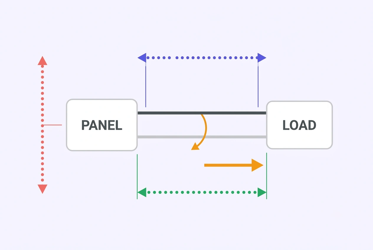
Circuit length. Current has to complete a loop, so the resistance that matters is the resistance of the whole loop, not of one conductor:
| System | Circuit Multiplier | Why |
|---|---|---|
| DC (two-wire) | 2 × one-way distance | Current leaves on the positive conductor and returns on the negative |
| AC single-phase | 2 × one-way distance | Current leaves on the ungrounded conductor and returns on the neutral |
| AC three-phase | 1.732 × one-way distance | Balanced phase currents sum to zero, so the neutral carries nothing and the loop factor is √3 |
Rearrange the equation for the conductor and you get the circular-mils shortcut that most electricians carry in their head:
cmil = (2 × K × I × D) ÷ Vdrop for DC and single-phase, and cmil = (1.732 × K × I × D) ÷ Vdrop for three-phase.
Here K is a resistivity constant — about 12.9 for copper and 21.2 for aluminum, both describing conductors at roughly 75 °C. Solve for cmil, then pick the first standard size on the chart at or above it. The shortcut and the resistance method are the same physics; the resistance method simply lets the operating temperature be whatever you say it is instead of fixed at 75 °C.
The ampacity side is a chain rather than a single formula. Start with the table value for the size and insulation rating, multiply by the ambient correction factor, multiply by the conductor-count adjustment, then cap the result at the lowest of the termination rating and any cable-type limit:
Ampacity = min( table × ambient factor × conductor factor, termination limit, cable-type limit )
Finally the overcurrent device. For a non-continuous load it is the first standard rating at or above the load current; for a continuous load or a motor branch circuit the load is multiplied by 125 percent first. NEC 240.6(A) fixes which ratings actually exist — you cannot specify a 37 amp breaker — and NEC 240.4(D) caps 14, 12, and 10 AWG far below their ampacity, which is why a 14 AWG conductor can never sit behind a 20 amp device.
Worked Examples
Example 1 — the page defaults. A 20 amp, 240 volt single-phase circuit; the panel is 50 feet from the equipment; copper THHN in conduit with three current-carrying conductors at 30 °C ambient and 75 °C terminations; a 3 percent drop limit.
The ampacity side caps each candidate at its 75 °C termination value: 14 AWG gives 20 amps and 12 AWG gives 25 amps. Either would carry 20 amps. But NEC 240.4(D) limits the overcurrent device on 14 AWG copper to 15 amps, and this circuit needs a 20 amp device, so 14 AWG is out on a rule that has nothing to do with the load. That leaves 12 AWG, whose 25 amp adjusted ampacity covers the 20 amp load with a 20 amp device.
The voltage drop confirms it fits comfortably: 12 AWG copper is 1.931 ohms per 1,000 feet at 75 °C, the loop is 100 feet (2 × 50), so the circuit resistance is 0.193 ohms. At 20 amps that is 3.86 volts lost, or 1.61 percent of 240 volts, leaving 236.14 volts at the load. Power dissipated as heat in the run is about 77 watts. The recommendation is 12 AWG copper with a 20 amp overcurrent device, and the same conductor could run up to about 93 feet one-way before the drop hit 3 percent.
Example 2 — the same load on 12 volts. Change only the system: 12 V DC, 15 amps, 25 feet one-way, 5 percent allowable drop, copper. Ampacity is no longer the issue at all — 14 AWG carries 20 amps. Voltage drop is a different story. The loop is 50 feet, so 14 AWG at 3.071 ohms per 1,000 feet loses 2.30 volts, which is 19 percent of 12 volts. 12 AWG still loses 12.1 percent, and 10 AWG still loses 7.6 percent. Only 8 AWG gets under the limit, at 4.77 percent — and the binding constraint flips to voltage drop, as the results panel will tell you.
What changed? The current went down and the distance went down, yet the conductor went up four sizes. A fixed number of lost volts is a trivial fraction of 240 volts and a devastating fraction of 12. Tighten that DC circuit to a 2 percent limit for a battery charger and 8 AWG fails too, pushing the answer to 6 AWG or 4 AWG. If a DC run keeps demanding absurd conductor sizes, the fix is usually to raise the system voltage to 24 or 48 volts, which cuts the current — and therefore the loss — in half or by three quarters.
AWG Wire Size and Resistance Chart
American Wire Gauge runs backwards: a lower number is a thicker conductor. Every three gauge steps roughly doubles the cross-sectional area and halves the resistance, which is why going up two sizes buys more than most people expect and going up one buys less. The resistance columns are at 20 °C; multiply by 1.22 for a conductor operating at 75 °C.
| AWG | Diameter (in) | Diameter (mm) | Area (kcmil) | Area (mm²) | Ω / 1,000 ft Copper | Ω / 1,000 ft Aluminum |
|---|---|---|---|---|---|---|
| 18 | 0.0403 | 1.024 | 1.62 | 0.823 | 6.385 | 9.832 |
| 16 | 0.0508 | 1.291 | 2.58 | 1.309 | 4.015 | 6.182 |
| 14 | 0.0641 | 1.628 | 4.11 | 2.081 | 2.525 | 3.888 |
| 12 | 0.0808 | 2.053 | 6.53 | 3.309 | 1.588 | 2.445 |
| 10 | 0.1019 | 2.588 | 10.4 | 5.261 | 0.9988 | 1.538 |
| 8 | 0.1285 | 3.264 | 16.5 | 8.366 | 0.6282 | 0.9673 |
| 6 | 0.1620 | 4.115 | 26.3 | 13.30 | 0.3951 | 0.6084 |
| 4 | 0.2043 | 5.189 | 41.7 | 21.15 | 0.2485 | 0.3827 |
| 3 | 0.2294 | 5.827 | 52.6 | 26.67 | 0.1970 | 0.3033 |
| 2 | 0.2576 | 6.544 | 66.4 | 33.63 | 0.1563 | 0.2407 |
| 1 | 0.2893 | 7.348 | 83.7 | 42.41 | 0.1239 | 0.1908 |
| 1/0 | 0.3249 | 8.251 | 105.5 | 53.48 | 0.0983 | 0.1514 |
| 2/0 | 0.3648 | 9.266 | 133.1 | 67.43 | 0.0779 | 0.1200 |
| 3/0 | 0.4096 | 10.405 | 167.8 | 85.03 | 0.0618 | 0.0952 |
| 4/0 | 0.4600 | 11.684 | 211.6 | 107.22 | 0.0490 | 0.0755 |
Note the pattern in the metric column: 4/0 AWG is about 107 mm² and 14 AWG is about 2.1 mm², a fifty-fold swing in copper area between the smallest branch-circuit conductor and the largest service conductor. In IEC regions the same conductor is simply sold as its metric area — 2.5, 4, 6, 10, 16, 25, 35, 50, 70, 95, 120 mm² — which is why a metric drawing may call out 6 mm² where a North American drawing calls out 10 AWG.
Ampacity and Derating Factors
The base ampacity table is short and gives three columns, one per insulation temperature rating. A conductor may not be loaded past the column that matches its insulation, and it may not be loaded past the temperature the equipment terminals can tolerate either.
| Size | Copper 60 °C | Copper 75 °C | Copper 90 °C | Aluminum 60 °C | Aluminum 75 °C | Aluminum 90 °C |
|---|---|---|---|---|---|---|
| 14 AWG | 15 A | 20 A | 25 A | — | — | — |
| 12 AWG | 20 A | 25 A | 30 A | 15 A | 20 A | 25 A |
| 10 AWG | 30 A | 35 A | 40 A | 25 A | 30 A | 35 A |
| 8 AWG | 40 A | 50 A | 55 A | 30 A | 40 A | 45 A |
| 6 AWG | 55 A | 65 A | 75 A | 40 A | 50 A | 55 A |
| 4 AWG | 70 A | 85 A | 95 A | 55 A | 65 A | 75 A |
| 2 AWG | 95 A | 115 A | 130 A | 75 A | 90 A | 100 A |
| 1/0 AWG | 125 A | 150 A | 170 A | 100 A | 120 A | 135 A |
| 4/0 AWG | 195 A | 230 A | 260 A | 150 A | 180 A | 205 A |
Where the ceiling really sits. A 90 °C THHN conductor in a 75 °C breaker does not become a 90 °C conductor; the connection is the weakest link and the ampacity ends at the 75 °C column. And NM-B cable is limited to the 60 °C column outright, even though the conductors inside it are marked 90 °C, because the cable assembly as a whole is not rated for the higher temperature. A 12 AWG NM-B conductor therefore tops out at 20 amps — exactly the breaker protecting it, with no margin to spend on anything.
Ambient temperature. Table ampacities assume 30 °C (86 °F). Hotter surroundings reduce how fast the conductor sheds heat, so the table value is multiplied down:
| Ambient | 60 °C Rated | 75 °C Rated | 90 °C Rated |
|---|---|---|---|
| 26 – 30 °C (79 – 86 °F) — base | 1.00 | 1.00 | 1.00 |
| 31 – 35 °C (88 – 95 °F) | 0.91 | 0.94 | 0.96 |
| 36 – 40 °C (97 – 104 °F) | 0.82 | 0.88 | 0.91 |
| 41 – 45 °C (106 – 113 °F) | 0.71 | 0.82 | 0.87 |
| 46 – 50 °C (115 – 122 °F) | 0.58 | 0.75 | 0.82 |
| 51 – 55 °C (124 – 131 °F) | 0.41 | 0.67 | 0.76 |
| 56 – 60 °C (133 – 140 °F) | — | 0.58 | 0.71 |
The empty cells matter as much as the numbers: a 60 °C conductor simply has no rating above 55 °C ambient. Run one through a 60 °C attic and the table gives you nothing to multiply.
Conductor count. Bundling conductors traps heat between them. Once more than three current-carrying conductors share a raceway or cable, the ampacity is adjusted:
| Current-Carrying Conductors | Adjustment |
|---|---|
| 1 – 3 | 100% |
| 4 – 6 | 80% |
| 7 – 9 | 70% |
| 10 – 12 | 50% |
| 13 – 15 | 45% |
| 16 – 20 | 40% |
| 21 – 30 | 35% |
| 31 – 40 | 35% |
| 41 or more | 35% |
Equipment grounding conductors never count toward this total, and neither do neutral conductors that meet the exception conditions for not being counted. Spare conductors that may be energized later do count. Two adjustments that each look harmless compound quickly: a 90 °C conductor carrying 35 amps in a 50 °C attic among eight current-carrying conductors becomes 35 × 0.82 × 0.70 = 20 amps, and it still has to clear the termination limit.
Typical Wire Gauge by Application
These are the pairings you will see on plans and in practice for copper conductors on short-to-moderate runs. They assume the overcurrent device named and no unusual derating; a long run, a hot location, or a bundle of conductors will push any of them up a size or two.
| Conductor | Typical Device | Common Use |
|---|---|---|
| 14 AWG copper | 15 A | Lighting circuits, bedroom and living-room receptacles |
| 12 AWG copper | 20 A | Kitchen counter, bathroom, garage, laundry receptacles |
| 10 AWG copper | 30 A | Electric dryer, water heater, air-conditioner disconnect, EV charger |
| 8 AWG copper | 40 A | Electric range, large HVAC equipment, small subpanel feed |
| 6 AWG copper | 50 – 60 A | Range and oven, hot tub, larger subpanel feed |
| 4 AWG copper | 70 – 85 A | Large subpanel, service equipment feeders |
| 2 AWG copper | 95 – 115 A | Main feeder to a small dwelling, large equipment |
| 1/0 – 4/0 copper | 125 – 260 A | Service entrance conductors, large feeders, parallel runs |
For aluminum, shift each row one size larger: 10 AWG aluminum where the table says 12 AWG copper, 8 AWG where it says 10 AWG, and so on. Service entrance conductors of 1/0 and larger are commonly aluminum, and long feeders are often aluminum purely on cost, with copper reserved for the terminations and short runs where its smaller size is worth the money.
| Standard Device Rating | Available Range |
|---|---|
| Small branch circuits | 15 · 20 · 25 · 30 · 35 · 40 · 45 · 50 A |
| Mid-size feeders | 60 · 70 · 80 · 90 · 100 · 110 · 125 A |
| Large feeders and services | 150 · 175 · 200 · 225 · 250 · 300 · 350 · 400 · 450 · 500 · 600 A |
Only these ratings exist. If a calculation says 37 amps, the device is a 40 — which is the whole reason the calculator rounds up to the ladder instead of reporting the raw number. The rounding is permitted by the next-standard-rating rule as long as the conductor ampacity is at least as high as the device being installed, with the 240.4(D) small-conductor caps still in force below 10 AWG.
Copper vs Aluminum
Aluminum has roughly 54 percent more resistance than copper for the same cross-section, so it needs one size larger to do the same job. Both a 10 AWG aluminum conductor and a 12 AWG copper conductor land near 30 amps on the 90 °C column, and both lose about the same voltage over the same run — the aluminum simply does it with a bigger, lighter, cheaper conductor.
| Property | Copper | Aluminum |
|---|---|---|
| Resistivity at 20 °C | 1.7241 × 10⁻⁸ Ω·m | 2.6548 × 10⁻⁸ Ω·m |
| Resistance for equal size | Baseline | About 54% higher |
| Temperature coefficient | 0.00393 / °C | 0.00403 / °C |
| Size for the same ampacity | Baseline | One size larger |
| Minimum permitted size | 14 AWG (branch circuits) | 12 AWG (most wiring) |
| Weight for equal ampacity | Heavier | Roughly half |
| Typical cost | Higher | Lower and more volatile |
| Terminations | Standard devices | Must be listed for aluminum |
Three practical cautions travel with aluminum. First, every termination must be listed for aluminum, and an anti-oxidant compound should be applied — aluminum oxide forms instantly on a cut end and is an insulator, and loose aluminum terminations have a habit of heating and loosening further. Second, aluminum work-hardens and is less forgiving of repeated bending, so it is a poor choice where a conductor will be flexed or re-terminated. Third, aluminum is not rated for submersible pump connections. Where aluminum earns its keep is long, high-current runs: a service lateral or a 200 amp feeder where one extra size costs far less than the copper it replaces.
Low-Voltage DC Circuits
Direct-current systems fail differently from mains wiring. On a 120 volt circuit, a 3.6 volt drop is a nuisance; on a 12 volt circuit, the same 3.6 volts is nearly a third of the supply and most equipment simply stops. That single ratio — absolute loss divided by system voltage — is why a wire sizing exercise that takes ten seconds on a household circuit can take an afternoon on a boat or a camper van.
The loss also compounds. Delivering 1,200 watts at 120 volts takes 10 amps; the same 1,200 watts at 12 volts takes 100 amps. Conductor loss rises with the square of current, so the low-voltage system dissipates one hundred times the heat in the same conductor while having a tenth of the voltage margin to absorb the resulting drop. Both halves of that sentence push the conductor size up.
Choosing a drop limit. Where a branch circuit uses 3 percent, DC practice varies by what is on the far end:
| Circuit | Sensible Drop Limit | Reason |
|---|---|---|
| Battery charging conductors | 2 – 3% | A charger must exceed battery voltage to push current in; lost volts cut charge current disproportionately |
| Electronics, controls, instrumentation | 3% | Inputs often specify a hard minimum around 10.5 – 11 V and will shut down below it |
| Lighting | 3 – 5% | Dimming is visible but rarely damaging; incandescent output falls faster than voltage because of the filament temperature |
| Motors and pumps | 3% running | Low voltage makes a motor draw more current and run hotter, which shortens its life |
| Engine starting circuits | Up to 10% momentary | The surge lasts seconds and the voltage sags anyway; sizing for it would be wasteful |
Do not assume the chassis is free. Vehicle wiring often uses the body or frame as the return path and then calculates drop on the positive conductor alone. That is correct only if the return really is near zero resistance. Corrosion, paint under a lug, a loose ground strap, or a long frame run can add tenths of an ohm, which on a 20 amp circuit is several volts gone before any conductor resistance is counted. Treat the return as a conductor of the same length when you are chasing a stubborn drop, and check the ground points themselves.
Connections are not free either. Every lug, terminal, fuse holder, and bus bar adds contact resistance. A few milliohms each sounds harmless until a circuit has ten of them, at which point they can exceed the resistance of the conductor they are attached to. In practice, loose and corroded connections cause more real-world voltage drop problems than under-sized conductors do.
When the conductor gets absurd, change the system. If a 12 volt run keeps demanding 4/0, the answer is usually not more copper. Doubling the system voltage to 24 volts halves the current and therefore halves the required cross-section; 48 volts roughly quarters it. A 1,500 watt inverter draws about 125 amps at 12 volts and only about 31 amps at 48 volts — the difference between 1/0 and 8 AWG for the same task.
One limitation to know about. This calculator uses the standard branch-circuit ampacity table, which begins at 14 AWG copper and 12 AWG aluminum. Small listed fixture and appliance wires of 16 and 18 AWG, and the ampacities other standards allow for them, fall outside that table — so for a very small DC load the calculator will return 14 AWG as a safe, code-aligned minimum rather than the smallest conductor those applications permit.
Common Wire Sizing Mistakes
Sizing the conductor to the breaker instead of the load. A 20 amp breaker does not mean the circuit needs a conductor good for 20 amps; it needs one good for the load, and the breaker exists to protect the conductor. When the load is 12 amps, putting a 20 amp device on the conductor does not make the circuit a 20 amp circuit — it just means the conductor is not protected as tightly as it could be.
Ignoring the round trip. Drop is calculated over the whole loop, so a 100 foot one-way run is 200 feet of conductor. Using the one-way distance halves the calculated drop and produces a conductor one or two sizes too small — a mistake that is invisible on paper and obvious at the far end of the run.
Forgetting that hot conduits derate. The ampacity table assumes 30 °C ambient and no more than three current-carrying conductors. A conduit crossing a sun-baked roof carried in a bundle of six conductors is outside both assumptions at once, and the 55 amp table value can legitimately become 33 amps. This is the single most common reason a "correct" calculation fails an inspection.
Assuming a 90 °C conductor gives 90 °C ampacity. The insulation may be rated for it, but the breaker terminals usually are not, and NM-B is capped at the 60 °C column outright. The conductor's rating is a ceiling, not an entitlement.
Rounding the device down. Standard ratings are a fixed list. When a calculation lands between two of them, the device goes up, never down — a 37 amp requirement is served by a 40 amp device, provided the conductor ampacity covers it.
Treating voltage drop as one number for the whole installation. The 5 percent allowance is the total from the service to the furthest outlet: 3 percent on the branch circuit plus 3 percent on the feeder already exceeds it. Sizing each segment to 5 percent individually can leave the last receptacle 9 percent low.
Upsizing the conductor without checking the device. Moving from 12 AWG to 10 AWG to fix a voltage drop problem also changes what overcurrent device the conductor can legally sit behind. A larger conductor behind the existing small breaker is fine electrically but has to be re-checked as a set before the inspection.
Burying the constraint. If the answer was forced by voltage drop rather than ampacity, a later change to the load current will behave in a way that surprises. The results panel names the binding constraint for exactly this reason — a voltage-drop-limited conductor has far more ampacity headroom than it appears to, and an ampacity-limited conductor has very little.
Frequently Asked Questions
A 20 amp branch circuit needs 12 AWG copper at minimum. That floor comes from two separate rules that happen to agree: the ampacity table gives 12 AWG copper 25 amps at 75 degrees Celsius, and NEC 240.4(D) caps a 20 amp circuit at 12 AWG copper or larger no matter how small the load is. If the run is long, voltage drop pushes the size up — a 20 amp circuit 50 feet from the panel is fine on 12 AWG, but past roughly 90 feet at a 3 percent drop limit you should step up to 10 AWG.
It depends on the current and how much drop you will accept. At 20 amps on a 120 volt circuit with a 3 percent limit, the ceiling is about 55 feet one-way. On a 240 volt circuit carrying the same 20 amps the limit roughly doubles to about 110 feet, because 3 percent of a larger voltage is a larger number of volts. Mains wiring is unforgiving this way: doubling the distance doubles the drop, so a run twice as long as the limit needs conductors two sizes larger, not one.
Both do, and the larger of the two answers wins. Ampacity keeps the conductor from overheating and protects the insulation; voltage drop keeps enough voltage arriving at the equipment. On short runs ampacity almost always binds. Past roughly 75 to 100 feet, voltage drop usually takes over and forces a size or two larger than the ampacity table alone would require. The calculator reports which of the two set your answer so you can see which way it went.
Voltage drop is a fixed number of volts for a given current, distance, and conductor. One volt lost is 1 percent of 120 volts but over 8 percent of 12 volts. Delivering the same wattage at 12 volts also takes ten times the current of 120 volts, and resistive loss rises with the square of current. That is why a 15 amp load 25 feet away in a van needs 8 AWG, while the same 15 amps a hundred feet away on a 120 volt circuit fits in 14 AWG. Moving the system up to 24 or 48 volts cuts the current in half or by three quarters and shrinks the conductor just as fast.
Multiply the load current by the conductor resistance and by the total circuit length, then compare that to the supply voltage. For DC and single-phase AC the current travels out and back, so the total length is twice the one-way distance; for three-phase it is 1.732 times the one-way distance. In the circular-mils shortcut the shape is drop equals 2 times K times current times one-way feet, divided by the conductor circular mils, where K is about 12.9 for copper and 21.2 for aluminum at 75 degrees Celsius.
Yes, but aluminum needs about one size larger than copper for the same ampacity and drop, because its resistivity is roughly 54 percent higher. Aluminum is not permitted below 12 AWG for most wiring, so a 14 AWG copper circuit has no aluminum equivalent. It is lighter and usually cheaper, which is why service entrance conductors and long feeders are often aluminum. Terminations must be listed for aluminum and should use an anti-oxidant compound, and aluminum is a poor choice anywhere the conductor will be flexed or where a submersible pump is involved.
Yes. The ampacity table assumes no more than three current-carrying conductors in a raceway at an ambient temperature of 30 degrees Celsius, and it drops as soon as either assumption breaks. Four to six conductors take an 80 percent adjustment, ten to twelve drop to 50 percent, and 21 or more fall to 35 percent. Ambient matters just as much: at 40 degrees Celsius a 90 degree rated conductor keeps 91 percent of its ampacity, at 50 degrees it keeps 82 percent, and at 60 degrees only 71 percent. Both adjustments multiply the table value, and the result is then capped by the termination rating.
References
- NFPA 70, National Electrical Code — Table 310.15(B)(16) conductor ampacities; Table 310.15(B)(2)(a) ambient correction; Table 310.15(B)(3)(a) conductor-count adjustment; 210.19(A) and 215.2(A) voltage drop guidance; 240.4(D) small-conductor overcurrent limits; 240.6(A) standard ampere ratings; 430.22 motor branch-circuit conductors, nfpa.org
- NFPA 70, National Electrical Code — Chapter 9, Table 8 conductor properties and DC resistance at 75 °C, the basis for the circular-mils constant K, nfpa.org
- American Boat and Yacht Council, ABYC E-11 — AC and DC Electrical Systems on Boats — conductor sizing and allowable voltage drop for DC systems, abycinc.org
- U.S. Department of Energy, Energy Saver — Electrical Safety and Energy Loss in Wiring, energy.gov
- Occupational Safety and Health Administration, Electrical Safety Standards for General Industry, osha.gov
This calculator provides planning estimates based on standard ampacity tables, published conductor resistance data, and the simplifying assumptions stated on this page. It does not replace a licensed electrician, an engineered design, or the adopted code edition and local amendments in force where you are working. Conductor selection also depends on conditions this tool cannot see — termination ratings, conduit fill, ambient temperature over the full length of the run, harmonics, and equipment-specific requirements. Verify all conductor and overcurrent device selections against NFPA 70 or your local code before installing. MyBuilderBase is not responsible for wiring decisions, inspection outcomes, or damage resulting from use of this tool.
Pulling a new circuit, feeder, or subpanel? Compare quotes from local licensed electricians before the wire goes in.
Get Free Estimates