
ON THIS PAGE:
Fastener Spacing at a Glance: The Numbers You Will Use Most
Five spacing patterns cover almost every residential panel and board job. Sheathing — roof, wall, and subfloor panels of plywood or OSB — is fastened 6 inches on center at supported panel edges and 12 inches on center at intermediate supports with 8d common nails for most roof panels and 6d or 8d for walls and floors, per IRC Table R602.3(1). Drywall runs 7 inches at ceiling edges and 12 inches in the field, 8 inches at wall edges and 16 inches in the field on 16-inch framing, opening to 16-and-16 or 16-and-24 when adhesive is applied — IRC Table R702.3.5. Deck boards take two #8 screws (or two 8d threaded nails) at every joist crossing, roughly 3.5 screws per square foot at 16-inch joist spacing — AWC's DCA 6 guide. Vinyl siding is capped at 16 inches on center for horizontal panels and 12 inches for vertical — IRC Section R703.11.1.3. Staples, where the schedule allows them, are 16-gage wire with at least a 7/16-inch crown, and panel schedules tighten staple rows to 4-and-8 or 3-and-6 instead of 6-and-12. Everything else on this page is a refinement of those five patterns: nail sizes by panel thickness, high-wind tightening on roof decks, glue-and-nail exceptions on floors, edge and end distances that keep fasteners out of the danger zone, and the member-to-member framing rows that hold the structure together before any panel arrives. Where a code table and a manufacturer's instruction disagree, the manufacturer's instruction for the product in your hands governs — check it first, then use the chart below.
Edge Spacing, Field Spacing, and the Vocabulary of Fastener Layout
Every fastener schedule in the building code is written in the same small vocabulary, and reading it correctly is most of the job.
On Center (o.c.)
All spacing figures are measured on center — center to center of one fastener to the next, never edge to edge. A row of 8d nails "at 6 inches o.c." puts the center of one nail 6 inches from the center of the next, which for an 8d common with a 0.131-inch shank leaves about 5-7/8 inches of clear wood between shanks. Layout is done with a tape and a mark, or with a chalk line snapped at the required distance, and the pattern is measured from a consistent reference (usually the panel corner) so the row closes cleanly at the far end.
Edge Spacing vs Field Spacing
Schedules list two numbers for a reason. Edge spacing applies along supported panel edges and ends — the perimeter row where the panel transfers load into framing and where seams meet. Field spacing (the code says "intermediate supports") applies at framing under the interior of the panel. Edges get the tighter number almost everywhere — 6 against 12 on sheathing, 7 or 8 against 12 or 16 on drywall — because the perimeter row is what resists racking, withdrawal, and edge lift. A third case sits between them: when a panel edge runs perpendicular to the framing and lands on no support at all, it gets fastened only where it crosses framing (and needs solid blocking wherever the code or the panel system calls for a fastened seam).
Toe-Nail, Face-Nail, End-Nail
Framing schedules specify not just the nail but the driving direction. A face nail goes straight through the face of one member into the other (stud to stud, plate to plate). A toe nail goes in at an angle through the corner where the members meet — the standard for studs to plates and rafters to top plates, usually with two nails on one side and one on the opposite side. An end nail goes through the end grain of one member into the other — the strongest orientation when there is room for it, used at splices and lap joints. Toe-nailing near the end of a board is the classic split-maker; the schedules keep those nail groups back from the edge for exactly that reason.
Penny Sizes and What the Letters Mean
Nail sizes in these tables are penny sizes written "d" — a holdout from an old system that priced nails by the penny per hundred. The number only tells you the length: 6d is 2 inches, 8d is 2-1/2 inches, 10d is 3 inches, 16d is 3-1/2 inches, 20d is 4 inches. Shank type matters as much as length: smooth common nails are the default in the code tables, deformed-shank nails have a knurled pattern for extra withdrawal resistance (the code's high-wind roof rows call for them), and ring-shank roofing nails (such as the RSRS-01 nails referenced in the IRC) grip like barbed wire in roof decks. Staples are specified by gage and crown: structural schedules want 16-gage wire with at least a 7/16-inch crown, while light cladding work allows smaller crowns.
| Size | Length | Where It Appears in These Schedules |
|---|---|---|
| 4d | 1½ in. | Fiber-cement panel siding driven direct to studs |
| 6d | 2 in. | ½-in. subfloor and wall sheathing; fiber-cement siding |
| 8d | 2½ in. | Roof sheathing; wall sheathing; framing toe-nails; deck threaded nails |
| 10d | 3 in. | 19/32- to 1-in. panels; framing lap and splice nails |
| 16d | 3½ in. | Wall plates, studs, corners, rafter-to-plate connections |
| 20d | 4 in. | Built-up beams and heavy framing |
Master Fastener Spacing Chart: Nails, Screws, and Staples by Material
This is the cross-material view: one row per application, the fastener the code or schedule calls for, and the two spacing numbers that govern the pattern. Read down to your material, then use the sections below for the full context — wind refinements, adhesive variants, penetration rules, and edge distances. All figures are maximums: a tighter pattern is always acceptable, and a looser one never is unless the manufacturer's approved instructions for the product say otherwise.
| Application | Fastener | Edge Spacing | Field Spacing | Source |
|---|---|---|---|---|
| Roof sheathing, 3/8–½ in. plywood/OSB | 8d common nail | 6 in. | 12 in. | IRC Table R602.3(1) |
| Wall sheathing, 3/8–½ in. | 6d common nail | 6 in. | 12 in. | IRC Table R602.3(1) |
| Subfloor, 3/8–½ in. | 6d common nail | 6 in. | 12 in. | IRC Table R602.3(1) |
| Panels, 19/32–1 in. (roof, wall, floor) | 8d common nail | 6 in. | 12 in. | IRC Table R602.3(1) |
| Panels, 1⅛–1¼ in. | 10d common or 8d deformed | 6 in. | 12 in. | IRC Table R602.3(1) |
| Sheathing at framing spans ≥ 48 in. | Same as row above | 6 in. | 6 in. | IRC Table R602.3(1) footnote |
| Roof sheathing, high-wind regions | 8d deformed where specified | 6 in. within 48 in. of ridge, eave, gable | 4 in. to gable-end framing | IRC Table R602.3(1) wind footnotes |
| Fiberboard sheathing, ½ in. | 1½-in. galv. roofing nail (7/16-in. head) or 16-ga. staple | 3 in. | 6 in. | IRC Table R602.3(1) |
| Gypsum sheathing, ½ and ⅝ in. | 1½/1¾-in. galv. roofing nail or Type W/S screw | 7 in. | 7 in. | IRC Table R602.3(1) |
| Drywall ceiling, no adhesive | Wallboard nail or Type W/S screw | 7 in. | 12 in. | IRC Table R702.3.5 |
| Drywall wall, 16-in. framing | Wallboard nail or Type W/S screw | 8 in. | 16 in. | IRC Table R702.3.5 |
| Drywall wall, 24-in. framing | Wallboard nail or Type W/S screw | 8 in. | 12 in. | IRC Table R702.3.5 |
| Drywall with adhesive | Wallboard nail or Type W/S screw | 16 in. | 16–24 in. | IRC Table R702.3.5 |
| Deck boards, each joist crossing | 2 × #8 screw or 2 × 8d threaded nail | 2 per crossing, ~¾–1 in. in from edge | — | AWC DCA 6 |
| Fiber-cement panel siding | 6d common (4d direct to studs) | 6 in. | 12 in. | IRC Table R703.3(1) |
| Hardboard panel siding | 0.120-in. nail, 0.225-in. head | 6 in. | 12 in. | IRC Table R703.3(1) |
| Vinyl siding, horizontal | 0.120-in. nail (0.313-in. head) or 16-ga. staple | 16 in. o.c. maximum, both directions (vertical siding: 12 in.) | IRC R703.11.1.3 | |
| Siding ≤ 3 psf over wood structural panel sheathing | Ring-shank 0.120-in. roofing nail or No. 6 screw | 12 in. o.c. (15 in. heavier ring-shank; 16 in. No. 8 screw) per 12 in. of siding width | IRC R703.3.3 | |
| Staples — roof panels | 16-ga., ≥ 7/16-in. crown | 3 in. | 6 in. | APA panel schedule |
| Staples — subfloor and wall panels | 16-ga., ≥ 7/16-in. crown | 4 in. | 8 in. | APA panel schedule |
| Framing — stud to stud (not at braced panels) | 16d common | 24 in. o.c. face nail | IRC Table R602.3(1) | |
Notes: Spacing is measured on center. "Edge" means supported panel edges and ends; "field" means intermediate supports under the panel. Fastener counts and hole positions must land on framing or required blocking — you cannot nail a panel edge that falls in mid-air, which is why seams are staggered or blocked. Roof rows reflect IRC Table R602.3(1) wind footnotes for regions above the table's base wind speeds; check the adopted code edition and local amendments for the exact wind-speed trigger in your area.
Framing Nailing Schedule: Member-to-Member Connections
Before any panel goes on, the frame itself is assembled to a nailing schedule: IRC Table R602.3(1) lists each connection — plate to plate, stud to stud, rafter to ridge — with the number and type of fastener and the driving direction. The rows below are the residential connections crews hit every day. The table offers alternatives within each row (box nails, common nails, 3-inch × 0.131-inch nails, even 14-gage staples in some connections); pick one line from the row and follow it exactly rather than mixing options.
| Connection | Fastener | Spacing / Pattern |
|---|---|---|
| Rafter or roof truss to top plate | 3-16d box or 3-10d common | Toe-nail: 2 on one side, 1 on the other, each rafter |
| Roof rafter to ridge, valley, or hip rafter | 4-16d box or 3-16d common | Toe-nail; end-nail option at laps |
| Collar tie to rafter | 3-10d common | Face nail, each rafter |
| Stud to stud (not at braced wall panels) | 16d common | 24 in. o.c. face nail |
| Stud to stud at braced panels / corner intersections | 16d common (16d box) | 16 in. o.c. (12 in. o.c. with box nails) |
| Top or bottom plate to stud | 3-16d box or 4-8d common | Toe-nail; end-nail option with 2-16d |
| Double top plate, end joints | 8-16d common | Face nail each side; minimum 24-in. lap each side of joint |
| Bottom plate to joist, rim joist, or blocking | 16d common (16d box) | 16 in. o.c. face nail (12 in. with box) |
| Joist to sill, top plate, or girder | 3-8d common, toe-nail — or 8d common | Toe-nail, or 8d at 6 in. o.c. toe-nail |
| Bridging or blocking to joist | 2-10d | Each end, toe-nail |
| 1-in. let-in brace to each stud and plate | 2-8d common | Face nail |
| 1×6 subfloor or less to each joist | 2-8d common | Face nail |
Two details in that table save the most rework. First, stud spacing tightens at braced wall panels and corner intersections — 16 inches on center instead of 24 — because those are the lines that carry shear. Second, double top plates offset their end joints by a minimum of 24 inches and get eight 16d nails at each lapped splice; stacking two joints in the same place is a classic framing inspection failure. For the nailing of panels onto this frame — the 6-and-12 pattern and its thickness-based nail sizes — see the roof, wall, and subfloor sections below.
Roof Sheathing Nail Spacing: 6 and 12, and When It Tightens
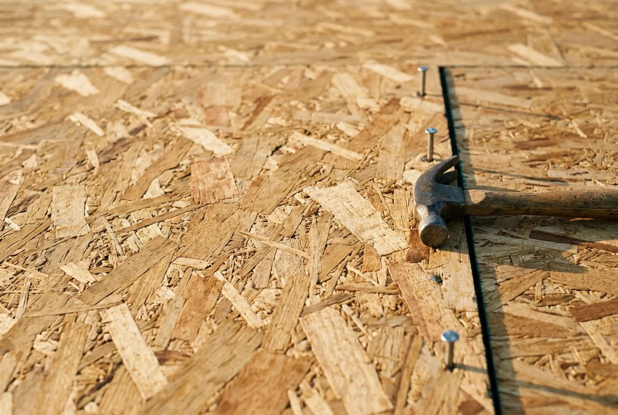
Roof deck nailing is the pattern most crews know by heart: 8d common nails at 6 inches on center along supported panel edges and 12 inches on center at intermediate rafters, from IRC Table R602.3(1) for plywood and OSB panels 3/8 to 1/2 inch thick (19/32- to 1-inch panels also take 8d at 6-and-12; 1-1/8- to 1-1/4-inch panels take 10d common or 8d deformed at the same spacing). Panels must be installed with all edges on rafters, ridges, hips, valleys, or required blocking — the code's fastener-spacing footnotes apply to supported edges, and seams are staggered so T-joints land on framing. The head of each nail is driven flush with the panel surface: over-driven heads cut the face veneer and lose holding power, proud heads tear the underlayment above them.
When the Pattern Tightens
Three conditions pull the numbers tighter than 6-and-12:
Long spans. Where framing spans reach 48 inches or greater, IRC Table R602.3(1) requires fasteners at all supports — not just edges — no farther apart than 6 inches on center.
High winds. The table's wind footnotes tighten roof nailing in regions above its base wind speeds: nails at intermediate supports within 48 inches of ridges, eaves, and gable ends go to 6 inches on center, and framing at gable ends goes to 4 inches on center; some wind zones also switch to 8d deformed-shank nails for the gable-zone attachment. Check the adopted code edition for the exact wind-speed trigger — it is stated in the table footnotes, and local amendments sometimes lower it further.
Ring-shank alternatives. The code allows approved ring-shank roof nails (specified as RSRS-01 nails meeting ASTM F1667) in place of smooth common nails — the same spacing, more withdrawal grip per nail, which is why ring-shank is the default on steep and coastal work.
Roof Panels Are Nailed, Not Glued
Unlike subfloors, roof sheathing is a nail-only assembly: panel manufacturers do not allow adhesive on roof decks, because the roof surface has to stay inspectable and repairable, and glued panels can telegraph movement into the covering above. Glue belongs on floors — see the subfloor section — and nails belong on roofs, at 6-and-12 until a footnote or a manufacturer's schedule says something tighter.
Subfloor Screw and Nail Spacing, With and Without Glue
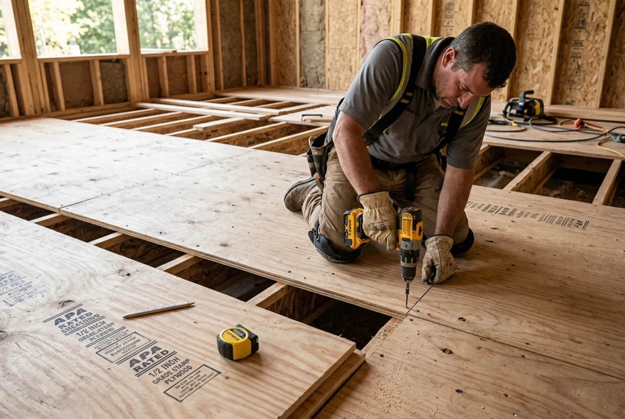
Subfloor panels follow the same spacing grid as wall sheathing — 6 inches at supported panel edges, 12 inches at intermediate supports — with the fastener size stepping up with panel thickness per IRC Table R602.3(1): 6d common nails for 3/8- to 1/2-inch panels, 8d common for 19/32- to 1 inch, and 10d common or 8d deformed for 1-1/8- to 1-1/4-inch panels. Panels run with their long dimension across the joists, ends staggered so no T-joint lines up with another, and every panel edge resting on framing or solid blocking — floor perimeters in particular must be supported by framing or blocking the whole way around.
Screws in Place of Nails
Screwed subfloors are standard practice now — screws do not back out, they pull the panel tight to the joist, and they hold squeak-free for the life of the floor. The catch: the code schedules are written in nails, so a screw is only as good as its approval for the assembly. Use subfloor or panel screws listed by the panel or fastener manufacturer for the thickness you are running, keep them on the same 6-and-12 grid, and drive them flush — the spacing grid never loosens just because the fastener has threads. Keep fasteners at least 3/8 inch back from panel edges per panel-maker guidance so the shank does not break out at the veneer.
Glue and Nail: The One Place Spacing Opens Up
The subfloor is the only residential panel assembly where the schedule deliberately relaxes. When panels are both glued and nailed — adhesive applied in a continuous bead per the panel manufacturer's instructions and conforming to ASTM D3498 or AFG-01 — manufacturer fastening schedules such as APA's allow the field spacing to widen, because the glue, not the nail pattern, is now carrying the panel between supports. Two rules keep the exception honest: spread the adhesive so every joist gets a full bond line, and set the nail (or screw) within the working time printed on the adhesive — once the glue skins over, the relaxed spacing no longer applies, and you are back to the code's 6-and-12. Where framing spans run 48 inches or more, fasteners at all supports stay at 6 inches or closer regardless of glue.
Worked Example: 12 × 16-Foot Shed Floor
A 12-by-16-foot floor is 192 square feet — exactly six 4×8 sheets. With joists at 16 inches on center, each sheet gets two supported edges at 6-inch spacing (9 fasteners per 4-foot edge) plus five interior joist lines at 12-inch spacing (5 fasteners per line): 18 + 25 = 43 fasteners per sheet, about 260 for the floor. Add a handful for blocking lines at staggered seams, and you know exactly how many pounds of fasteners to buy before the first sheet is cut.
Drywall Screw Spacing: The IRC Table, Explained
Gypsum board spacing lives in its own table — IRC Table R702.3.5 — because drywall is a finish material with different load paths than structural sheathing. The table gives one spacing pair per row that applies to both nails and screws: fastener spacing is listed once, and the nail or screw size is the variable. Three rules frame every row: all board edges and ends must land on framing members (the only exception is edges running perpendicular to framing, which may fall between members), fasteners stay at least 3/8 inch back from panel edges and ends, and screws must be Type W or Type S to ASTM C1002, penetrating the wood at least 5/8 inch.
Without Adhesive
| Board | Application | Framing o.c. | Edges | Field |
|---|---|---|---|---|
| ⅜ in. | Ceiling | 16 in. | 7 in. | 12 in. |
| ⅜ in. | Wall | 16 in. | 8 in. | 16 in. |
| ½ in. | Ceiling | 16 or 24 in. | 7 in. | 12 in. |
| ½ in. | Wall | 16 in. | 8 in. | 16 in. |
| ½ in. | Wall | 24 in. | 8 in. | 12 in. |
| ⅝ in. | Ceiling | 16 or 24 in. | 7 in. | 12 in. |
| ⅝ in. | Wall | 16 in. | 8 in. | 16 in. |
| ⅝ in. | Wall | 24 in. | 8 in. | 12 in. |
| ⅝ in. Type X, garage ceiling under habitable rooms | Ceiling | 24 in. | 6 in. | 6 in. |
With Adhesive
Construction adhesive applied to the framing before hanging lets the pattern open up — the glue takes the bond the extra nails were providing. Without adhesive at the ceiling, the table also allows paired nails in place of single fasteners: two nails spaced 2 to 2-1/2 inches apart, with each pair at 12 inches on center.
| Board | Application | Framing o.c. | Edges | Field |
|---|---|---|---|---|
| ⅜ in. | Ceiling | 16 in. | 16 in. | 16 in. |
| ⅜ in. | Wall | 16 in. | 16 in. | 24 in. |
| ½ or ⅝ in. | Ceiling | 16 in. | 16 in. | 16 in. |
| ½ or ⅝ in. | Ceiling (perpendicular) | 24 in. | 12 in. | 16 in. |
| ½ or ⅝ in. | Wall | 24 in. | 16 in. | 24 in. |
| Two ⅜-in. layers | Ceiling | 16 in. | 16 in. | 16 in. |
| Two ⅜-in. layers | Wall | 24 in. | 24 in. | 24 in. |
Code Maximums vs Field Practice
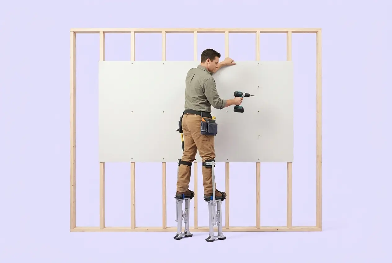
The numbers above are the code maximums — the widest spacing an inspector should see. Common field practice, drawn from gypsum application standards such as ASTM C840 and manufacturer installation guides, typically cites screws no farther apart than about 12 inches on ceilings and 16 inches on walls at 16-inch framing, and about 12 inches throughout at 24-inch framing. In practice most hangers run tighter than both: ceiling screws every 8 to 10 inches and wall screws every 8 to 12 along each stud, because the extra fasteners cost seconds and eliminate exactly the ceiling sag and corner cracks the maximums are designed to prevent. When a hanging crew and an inspector disagree, the adopted code table is the floor and the manufacturer's instruction is the target — go tighter, not looser.
Deck Screw Spacing: Two Fasteners at Every Joist
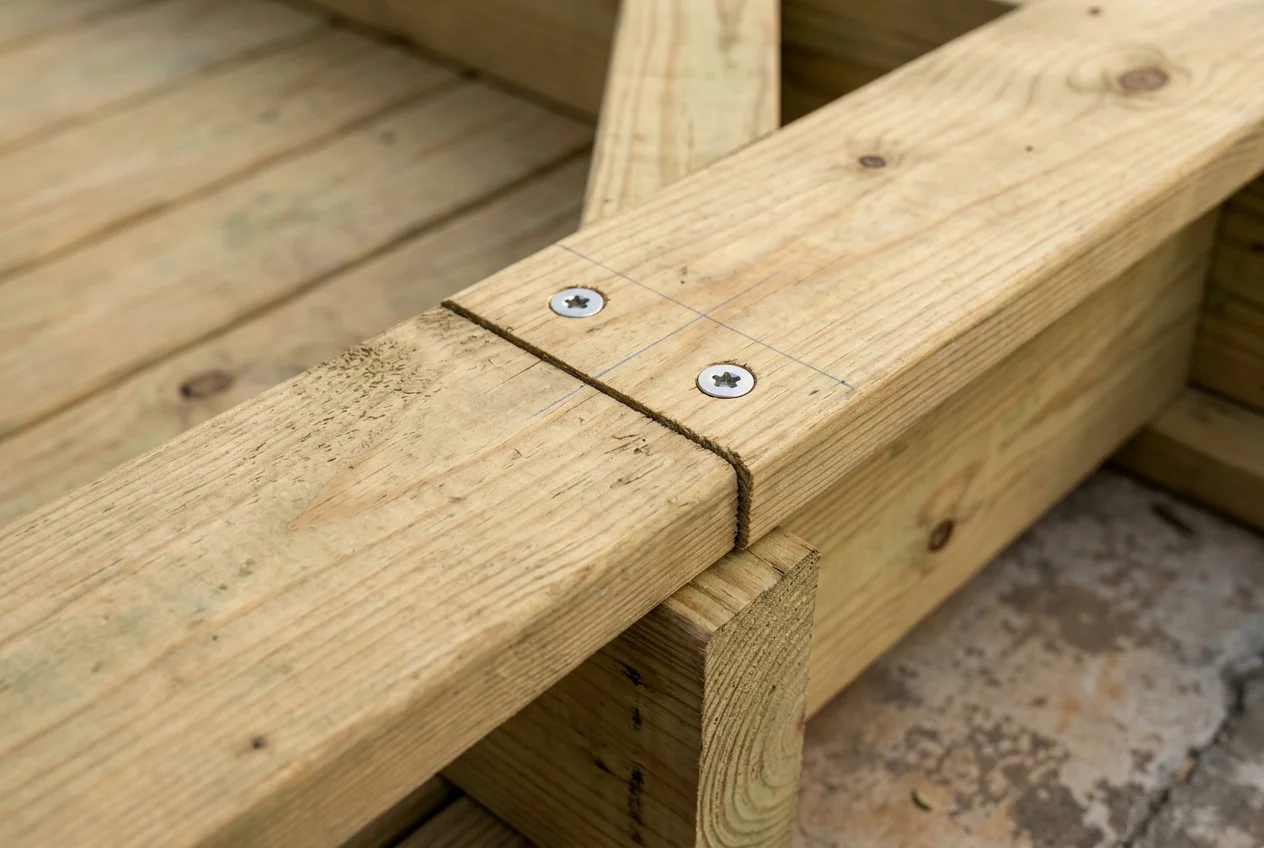
Decking is the rare surface with a count rule instead of a spacing grid: AWC's DCA 6 prescriptive deck guide requires each board to be attached to each joist with two #8 screws (or two 8d threaded nails), with boards gapped approximately 1/8 inch apart for drainage and each deck board segment bearing on a minimum of three joists. The spacing of the two screws across the board width is left to good judgment and the board manufacturer — set them evenly in from each edge, typically about 3/4 to 1 inch, and hold them back about 1-1/2 inches from board ends so the heads seat on the chamfer instead of splitting it.
From "Two per Joist" to Screws per Square Foot
The two-per-joist count converts to a per-area number through joist spacing and board width. At 16 inches on center with 5-1/2-inch-wide boards (2×6 or 5/4×6), a 12-by-16-foot deck needs about 3.5 screws per square foot: 13 joists × 26 boards × 2 screws ≈ 676 screws for 192 square feet. At 24 inches on center the same deck drops to about 2.5 per square foot — fewer crossings, fewer screws — which is why the joist layout, not the board length, drives the fastener count. Composite and plastic boards follow the same two-per-crossing pattern with the manufacturer's own screw and spacing requirements, and span-rated decking must still meet the span rating printed on the product.
The Ledger: Where Deck Spacing Gets Serious
The one deck connection with a real spacing table is the ledger — the board that ties the deck to the house. DCA 6 sets ledger lag-screw and bolt spacing from the joist span: short spans allow fasteners as far apart as about 24 inches on center, and as spans lengthen the spacing tightens down toward about 8 inches. Placement matters as much as the interval: fasteners run in two staggered rows kept at least 2 inches in from the ledger's top and bottom edges, rows spaced between roughly 1-5/8 and 5 inches apart, no fastener closer than about 5 inches to the ledger's end, with lag-screw tips extending fully through the house band joist. A ledger nailed at one row along its centerline — a common sight on older decks — has none of the split resistance or lever-arm width the spacing table assumes.
Siding Nail Spacing: Vinyl, Fiber Cement, Wood, and Shakes
Exterior cladding is the one family where the spacing rule changes with the product family — and where the manufacturer's installation instructions, incorporated by reference into IRC Chapter 7, routinely govern over anything printed in a general table. The IRC's own limits still frame every job:
Vinyl Siding
Unless the manufacturer says otherwise, IRC R703.11.1.3 caps fastener spacing at 16 inches on center for horizontal siding and 12 inches — horizontally and vertically — for vertical siding, with wider spacing allowed only when the manufacturer's instructions and a test report support it. Fasteners are 0.120-inch shank nails with 0.313-inch heads, or 16-gage staples with 3/8- to 1/2-inch crowns, driven through the nailing slot — never through the panel face — and penetrating at least 1-1/4 inches into the framing (or into the substrate per the manufacturer's test report when foam or other sheathing is in the assembly). Leave the nail shy of tight so the panel can slide with temperature: a pinioned vinyl panel puckers at every fastener.
Fiber Cement and Hardboard Panels
Per IRC Table R703.3(1), fiber-cement panel siding takes 6d common nails at 6 inches on panel edges and 12 inches at intermediate supports (4d common when nailing direct to studs); hardboard panel siding uses 0.120-inch nails with 0.225-inch heads at the same 6-and-12 pattern. Fiber-cement lap siding uses 6d common nails (or 11-gage roofing nails in the foam-sheathing column) with fasteners at each stud per course, and penetration into framing must be at least 1-1/2 inches for wood, hardboard, and fiber-cement siding alike.
Siding Over Wood Structural Panel Sheathing
For lightweight siding (3 pounds per square foot or less) attached over wood structural panel sheathing — over foam of 2 inches or less, or directly — IRC R703.3.3 gives its own table: ring-shank roofing nails of 0.120-inch minimum diameter at 12 inches on center, heavier 0.148-inch ring-shank nails at 15 inches, No. 6 screws at 12 inches, and No. 8 screws at 16 inches — all per 12 inches of siding width, scaled by 12 divided by your actual width for other exposures, and never spaced wider than the cladding manufacturer's own minimum. Fasteners must be corrosion-resistant (galvanized or stainless, meeting ASTM F1667), and the nail must reach through the sheathing into framing or, where the table allows it, into the sheathing itself with at least 1/4 inch of tip projecting past the back face.
Wood Siding and Shakes
Wood plank siding follows IRC R703.5.3: face nailing with one 6d common through the overlapping planks at each stud, or concealed nailing with one 11-gage 1-1/2-inch galvanized roofing nail through the top edge of each plank at each stud. Wood shakes and shingles get two fasteners per shake, placed so the course above covers them — in single-course application the fastener is hidden about 1 inch above the butt line of the next course and about 3/4 inch from the shake edge; in double-course work the exposed course is face-nailed with two fasteners about 2 inches above the butt line and 3/4 inch from each edge. Shakes take stainless Type 304 or 316 or hot-dip galvanized box nails, or 16-gage stainless staples with 7/16-inch minimum crowns set parallel to the butt, driven at least 1/2 inch into the sheathing — never overdriven.
Staple Spacing for Plywood and Panel Products
Wherever a schedule lists nails for panels, it usually lists an allowed staple alternative — and the staple pattern is tighter, because a staple's crown distributes hold over two legs instead of one shank. The IRC's framing table sets the floor of the rule: structural staples are 16-gage wire with a minimum 7/16-inch crown, driven with a pneumatic stapler set to leave the crown flush. Panel schedules then give the actual grid:
| Application | Staple | Edge Spacing | Field Spacing |
|---|---|---|---|
| Roof sheathing panels | 16-ga., ≥ 7/16-in. crown | 3 in. | 6 in. |
| Subfloor and wall panels | 16-ga., ≥ 7/16-in. crown | 4 in. | 8 in. |
| ½-in. fiberboard sheathing | 1¼-in. long, 16-ga., 7/16- or 1-in. crown | 3 in. | 6 in. |
| ½-in. gypsum sheathing | 1½-in. long, galvanized | 7 in. | 7 in. |
| Exterior lath (stucco base) | ⅞-in. long, 16-ga. | 6 in. maximum, both directions | |
| Vinyl siding (alternative to nails) | 16-ga., ⅜–½-in. crown | 16 in. horizontal / 12 in. vertical maximum | |
Three practical notes. The roof staple pattern — 3-and-6 — is exactly half the nail pattern, reflecting the lower withdrawal resistance of a staple leg versus a nail shank; don't "substitute equivalent" by keeping 6-and-12 with staples. Staples used for sheathing want the full 7/16-inch crown minimum from the code table, while staples for light cladding like vinyl are allowed smaller 3/8- to 1/2-inch crowns because they are holding a panel in a slot, not resisting uplift. And crown orientation matters on board products: staples go across the grain direction of the panel so the crown bridges fibers rather than splitting along them — the reason shake installation standards call for staple crowns set parallel to the butt of the shake.
Edge Distance, End Distance, and Keeping Fasteners Off the Edge
Spacing tells you where fasteners go in a row; edge and end distances tell you how close they may come to the boundary of the material — the number that decides whether the wood splits or the fastener blows out the side. Every assembly in this guide carries its own minimum:
| Assembly | Minimum From Edge / End | Source |
|---|---|---|
| Drywall board edges and ends | ⅜ in. | IRC Table R702.3.5 notes |
| Plywood / OSB panel edges (panel-maker guidance) | About ⅜ in. | Panel manufacturer instructions |
| Deck board fasteners (practice) | ~¾–1 in. from edge; ~1½ in. from ends | Board manufacturer instructions |
| Wood shake edges | ¾ in. from edge | IRC R703.6.3 |
| Ledger lag screws (DCA 6) | ≥ 2 in. from top and bottom edges; ≤ ~5 in. from board end | AWC DCA 6 figures |
| Structural fasteners, general (NDS diameter multiples) | ~4D between fasteners; ~7D from a loaded end in tension; ~1.5D from an edge | AWC NDS Table 12.5.1 |
The NDS row deserves one sentence of context: for structural dowel-type fasteners a quarter-inch and larger, the National Design Specification expresses minimum spacing, edge, and end distances as multiples of the fastener diameter (D) — roughly four diameters between fasteners, seven diameters from an end loaded in tension (four unloaded), and about one and a half diameters from an edge — so the same rule scales from a small screw to a heavy bolt. Prescriptive tables like the ones elsewhere on this page bake these multiples in already; the diameter math is what to reach for when a connection falls outside the tables and needs real design.
Two field habits cover most split damage. First, start fasteners back from the end: end grain is the weakest direction in wood, and a nail close to the tip of a board acts as a splitting wedge — hold at least a fastener-and-a-half's worth of clearance back from board ends, and pre-drill whenever a fastener must land closer than that or when toe-nailing near a plate end. Second, hold the spacing from a consistent reference: measure each row from the panel corner or the board end, not from the previous nail, because a 6-inch row that drifts accumulates its error exactly where the seam is weakest. When a row closes short at the far end, add fasteners — never stretch the pattern to make the last nail land.
How Many Fasteners Do You Need? Formulas and Worked Examples
Spacing converts to a shopping list through two formulas. For a straight run — one edge, one seam, one joist line — the count is simple:
Fasteners per run = run length ÷ spacing + 1
For a rectangular perimeter, count each side with that formula and subtract the four corners so they are not counted twice:
Perimeter count = 2 × (L ÷ s + 1) + 2 × (W ÷ s + 1) − 4
Then add the field: one fastener at each framing line under the panel, spaced per the field number along that line.
Example 1 — Subfloor Sheet on 16-Inch Joists
One 4×8 sheet, joists at 16 inches on center, long dimension across the joists. The two edges that land on joists run 4 feet each at 6-inch spacing: 48 ÷ 6 + 1 = 9 fasteners per edge, 18 total. Five interior joist lines fall under the sheet, each fastened at 12 inches over the 4-foot width: 48 ÷ 12 + 1 = 5 per line, 25 total. 18 + 25 = 43 fasteners per sheet. A 12×16-foot floor is 192 square feet — six sheets — so 6 × 43 ≈ 260 fasteners, plus a small allowance for blocking lines. (Add blocking along a fully supported perimeter edge and every extra 8-foot blocked edge adds about 17 more at the 6-inch pattern.)
Example 2 — Deck Screws for a 12 × 16-Foot Deck
Joists at 16 inches on center over the 16-foot dimension: 16 × 12 ÷ 16 + 1 = 13 joists. Boards 5-1/2 inches wide covering the 12-foot run: 12 × 12 ÷ 5.5 ≈ 26 boards. Two screws at every crossing: 13 × 26 × 2 = 676 screws for 192 square feet — 676 ÷ 192 ≈ 3.5 screws per square foot. The same deck at 24-inch joists drops to 9 joists, 468 screws, about 2.5 per square foot. Round both counts up to the box: fasteners are cheap compared with a second trip, and a 3-to-5-percent spare on top of the count is standard practice for drops and miscuts.
Example 3 — Roof Deck at 24-Inch Rafters
Same sheet, rafters at 24 inches: two supported edges at 9 each plus three interior rafter lines at 5 each gives 18 + 15 = 33 fasteners per sheet. A 1,200-square-foot roof deck (1,200 ÷ 32 = 37.5 → 38 sheets) runs 38 × 33 ≈ 1,250 nails — before any high-wind tightening within 48 inches of the ridge, eave, or gable end, which can raise the count meaningfully in the worst zone of the roof. For live arithmetic on sheet counts, the Plywood Calculator and Roof Sheathing Calculator handle the panels; the fastener math above is the same arithmetic they feed.
Frequently Asked Questions
For plywood and OSB roof, wall, and subfloor sheathing, the standard spacing from IRC Table R602.3(1) is 6 inches on center at supported panel edges and 12 inches on center at intermediate supports, with the nail size set by panel thickness: 6d common nails for 3/8- to 1/2-inch panels (8d common for roof sheathing), 8d common nails for 19/32- to 1-inch panels, and 10d common or 8d deformed nails for 1-1/8- to 1-1/4-inch panels. Where framing spans are 48 inches or greater, fasteners at all supports tighten to 6 inches on center, and higher-wind regions require closer roof nailing — 6 inches within 48 inches of ridges, eaves, and gable ends, and 4 inches into gable-end wall framing.
IRC Table R702.3.5 sets drywall fastener spacing at 7 inches on center at panel edges and 12 inches across the field for ceilings, and 8 inches at edges and 16 inches across the field for walls framed 16 inches on center — the wall field widens to 12 inches when framing is at 24 inches. With adhesive, spacing opens to 16 inches at edges and 16 to 24 inches in the field, and Type X gypsum board over a garage ceiling beneath habitable rooms takes fasteners every 6 inches in both directions. Fasteners stay at least 3/8 inch from panel edges and ends, every board edge must land on a framing member, and screws must be Type W or Type S to ASTM C1002 penetrating the wood at least 5/8 inch.
Subfloor fasteners follow the same 6-inch edge, 12-inch field grid as other panel sheathing: 6d common nails for 3/8- to 1/2-inch panels, 8d common for 19/32- to 1-inch panels, and 10d common or 8d deformed for 1-1/8- to 1-1/4-inch panels, per IRC Table R602.3(1). Screws installed instead of nails must be of a type approved for the assembly — the spacing grid does not change. When panels are both glued and nailed with an adhesive conforming to ASTM D3498 or AFG-01, manufacturer schedules such as APA's allow the field spacing to open up, and where framing spans are 48 inches or greater, fasteners at every support stay at 6 inches or closer.
Two fasteners at every joist crossing. AWC's DCA 6 deck guide requires each deck board to be attached to each joist with two #8 screws (or two 8d threaded nails), with boards gapped about 1/8 inch and each board bearing on at least three joists. At 16-inch joist spacing that works out to roughly 3.5 screws per square foot for 5-1/2-inch-wide boards, and about 2.5 per square foot at 24-inch spacing. Set the pair in from the board edges evenly — typically about 3/4 to 1 inch — and back about 1-1/2 inches from board ends so the heads seat without splitting the chamfer, and follow your deck board manufacturer's instructions for exact edge and end distances.
Unless the manufacturer's instructions say otherwise, IRC Section R703.11.1.3 limits vinyl siding fasteners to a maximum of 16 inches on center for horizontal siding and 12 inches on center — horizontally and vertically — for vertical siding, and greater spacing is allowed only when the manufacturer's instructions and a test report support it. Fasteners are 0.120-inch shank nails with 0.313-inch heads or 16-gage staples with 3/8- to 1/2-inch crowns, and they must penetrate at least 1-1/4 inches into the framing. Fasteners go through the nailing slot rather than the panel face so the siding can move with temperature changes.
Panel edges and ends are where load transfers into the framing and where racking forces concentrate, so the perimeter row of fasteners does most of the structural work — which is why sheathing schedules call for 6 inches at supported edges against 12 inches in the field, and why drywall takes 7 or 8 inches at edges against 12 or 16 inches in the field. Interior fasteners mainly keep the panel flat and stop flutter between supports. Widening the perimeter pattern invites edge lift, buckling along seams, and withdrawal under load; essentially every published panel schedule is tighter at the perimeter for that reason.
Often, yes — but the screw must be approved for that specific assembly, and the spacing grid does not widen. Drywall screws must be Type W or Type S to ASTM C1002 with at least 5/8 inch of penetration into wood; deck boards need #8 screws at two per joist; sheathing screws must be listed for the panel system by the panel or screw manufacturer; and siding fasteners must match IRC Table R703.3(1) or the cladding manufacturer's instructions. What screws never do is buy a wider pattern — if the schedule says 6 and 12 inches, screws go at 6 and 12 inches unless the approved assembly says otherwise.
Every skipped fastener shifts load onto the ones nearby. Panel edges lift at seams, panels flutter and squeak between supports, drywall sags at ceilings, and under wind or seismic load the assembly can no longer act as the diaphragm the code assumed. Inspectors check spacing patterns as literal code compliance: a sheet with its edges nailed at 16 inches fails inspection even if the sheet itself is perfect. The fix is cheap during installation — another nail along the seam — and expensive afterward, because the panel has to come back out.
References
- International Code Council, International Residential Code (IRC) — Table R602.3(1) fastening schedule for structural members, Table R702.3.5 gypsum board spacing, Sections R702.3.5.1, R703.3.3, R703.3.4, R703.5.3, R703.6.3, and R703.11.1 — iccsafe.org.
- APA — The Engineered Wood Association, Recommended Minimum Fastening Schedules for Wood Structural Panels — panel nail and staple spacing for roof, wall, and subfloor applications, and glue-and-nail floor schedules referencing ASTM D3498 and AFG-01 adhesives — apawood.org.
- American Wood Council, DCA 6: Prescriptive Residential Wood Deck Construction Guide — two #8 screws or two 8d threaded nails per joist, 1/8-inch board gap, three-joist bearing rule, and ledger fastener spacing and placement figures — awc.org.
- American Wood Council, National Design Specification (NDS) for Wood Construction — minimum spacing, edge, and end distances for dowel-type fasteners expressed as fastener-diameter multiples (Table 12.5.1) — awc.org.
- ASTM International, ASTM C1002 (Type W and Type S drywall screws), ASTM C840 (gypsum board application practice), ASTM F1667 (driven fasteners), and ASTM D3498 (adhesives for glue-nailed panels) — astm.org.
- Vinyl Siding Institute, Vinyl siding installation instructions and testing references cited by IRC Section R703.11 for fastener type, slot placement, and spacing — vinylsiding.org.
- Building-industry trade practice on edge-and-field nailing patterns, toe-, face-, and end-nailing conventions, penny-size nail nomenclature, and fastener-count estimating used across residential framing and finish work.
Disclaimer: This guide compiles published fastener spacing requirements — IRC tables, APA panel schedules, AWC deck guidance, and common trade practice — for general educational use across residential work. It is not a substitute for the code edition adopted in your jurisdiction, the manufacturer's written installation instructions for the product you actually bought (which govern), or project-specific engineering. Wind speeds, seismic design categories, product approvals, and local amendments all change these numbers; verify spacing against your adopted code and the fastener, panel, and cladding instructions before installation, and consult a licensed professional for structural, diaphragm, or high-wind conditions.